Original content by the OOTEE Optics editorial team, drawn from first-hand production line and inspection data. Please credit the source when republishing.
Given limits in expertise and test conditions, the theories, parameters and conclusions here carry no guarantee of absolute accuracy. For technical learning and exchange only - never the sole basis for design, acceptance or selection. Corrections welcome.
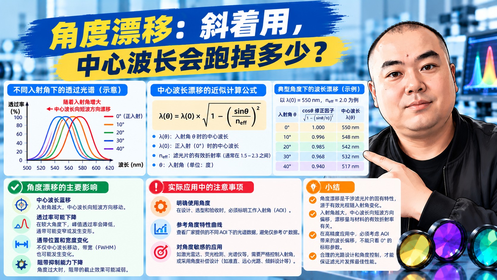
Angular shift is how far the center wavelength or edge moves as the angle of incidence changes, expressed in nm for a given angle or in nm per degree.
It is the classic reason why a filter looks perfect in the lab and fails in the field: the curve was measured at 0 degrees while your instrument feeds light in at an angle.
Interference filters select wavelength through constructive interference inside the coating stack. At an angle the geometric path inside the layers lengthens, but the component along the normal - the one that sets the interference condition - shrinks. The layers behave as if they were optically thinner, so the wavelength that interferes constructively becomes shorter. That is the blue shift.
At small angles a simple approximation works well:
lambda(theta) approx lambda0 times the square root of (1 - sin-squared theta / n_eff squared)
where lambda0 is the center wavelength at normal incidence and n_eff is the effective index of the stack, typically 1.5-2.0 for visible narrowband filters.
| Angle | CWL 532 nm narrowband (n_eff about 1.8) | Practical impact |
|---|---|---|
| 0 degrees | 532.0 nm | Nominal |
| 5 degrees | about 531.8 nm | Negligible |
| 10 degrees | about 531.0 nm | Becomes noticeable below 5 nm bandwidth |
| 20 degrees | about 528 nm | Must be compensated |
| 45 degrees | about 500 nm or shorter | Must be designed for 45 degrees from the start |
Note: the narrower the bandwidth, the more a given shift hurts. Two nanometers is invisible for a 40 nm wide filter and fatal for a 1 nm Raman filter.
With a converging cone (say +/-8 degrees behind a lens) you do not have one angle but a weighted spread. Consequences:
That is why high numerical aperture fluorescence systems and fiber-coupled setups generally specify flat-top curves: there is no peak to flatten in the first place.
Recommended: "Operating condition: AOI 15 degrees with a +/-5 degree cone; CWL 531 +/- 1 nm and Tmin at least 80% under that condition."
Put the operating condition first and the maker can design the stack and inspect the curve against it. Specifying only 0 degrees leaves the risk with you.
Not sure what equivalent angle your instrument imposes? Send a sketch of the optical path to sales@ootee.cn and we will estimate the shift and propose compensation.
 365nm Narrow Bandpass Filter | Ø50mm | T>90%
OT-HBP3659050
365nm Narrow Bandpass Filter; FWHM 10nm; transmission >90%; blocking OD5; size Ø50mm; AOI 0°.
 450nm Narrow Bandpass Filter | Ø50mm
OT-HBP4509050
450nm Narrow Bandpass Filter; FWHM 10nm; transmission >90%; blocking OD5; size Ø50mm; AOI 0°.
 525nm Narrow Bandpass Filter | Ø50mm
OT-HBP5259050
525nm Narrow Bandpass Filter; FWHM 10nm; transmission >90%; blocking OD5; size Ø50mm; AOI 0°.
Send us your drawing and spectral targets — an engineer replies with a feasibility check and quotation within one business day.



