Original content by the OOTEE Optics editorial team, drawn from first-hand production line and inspection data. Please credit the source when republishing.
Given limits in expertise and test conditions, the theories, parameters and conclusions here carry no guarantee of absolute accuracy. For technical learning and exchange only - never the sole basis for design, acceptance or selection. Corrections welcome.
An optical filter depends on thin films bonded to a substrate. Anti-delamination treatment is a process strategy: surface preparation, activation, initial-layer design and deposition control work together to maintain adhesion. It does not identify a universal chemical treatment or imply that glue is applied to the finished optic.
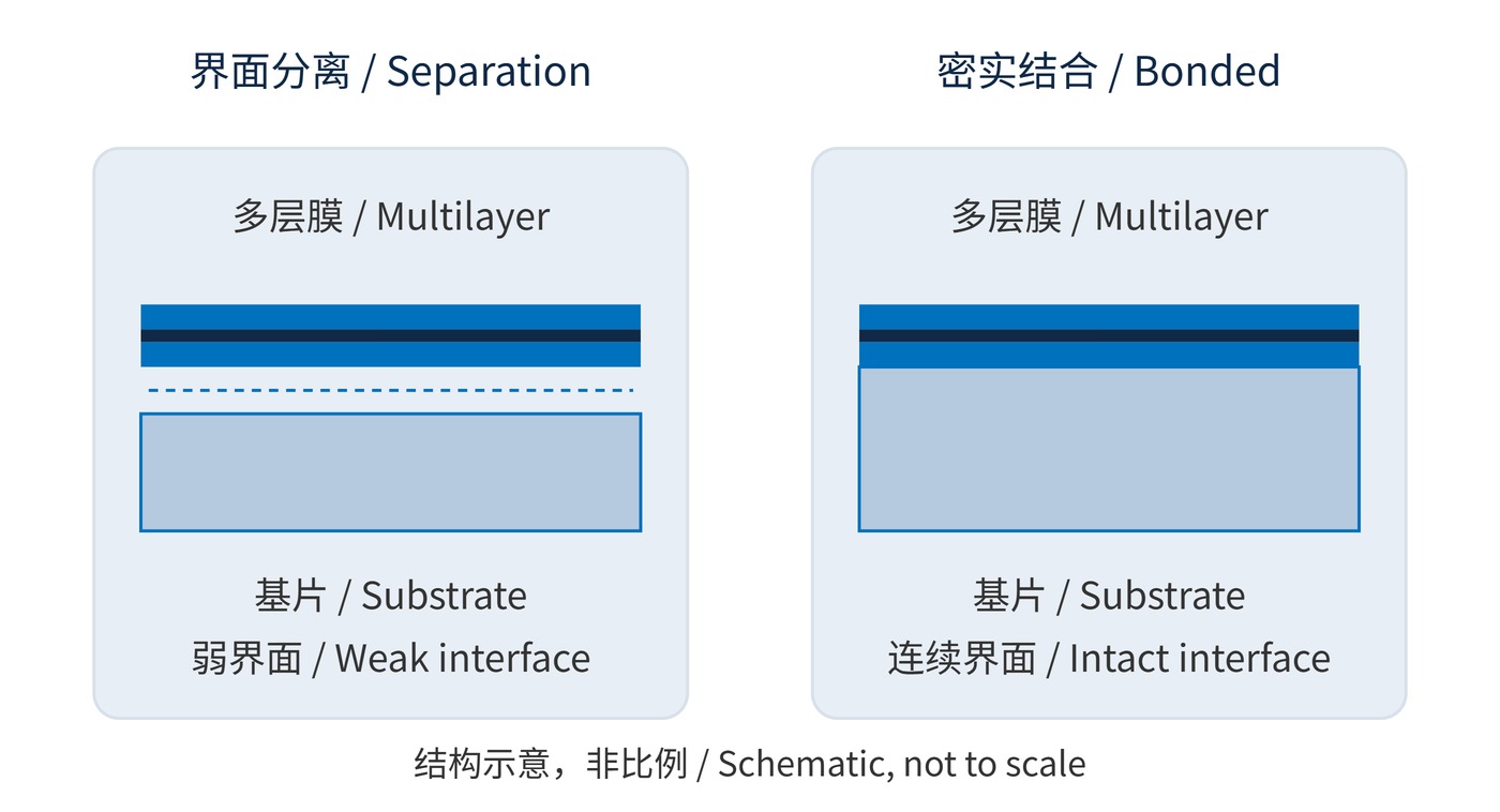
Delamination occurs when a crack advances along an interface. A crack within a layer or a scratch on its surface is a different failure. Fig. 1 distinguishes a separated interface from a bonded one. Finding the fracture location matters because a harder outer surface cannot repair a weak buried interface.
A pristine appearance at delivery is insufficient evidence of durable adhesion. Local contamination can leave weak regions even when the initial spectrum passes inspection. Handling, mounting or a temperature change may subsequently activate those defects.
Organic residues, adsorbed water and particles can interrupt bonding and seed cracks. Cleaning, drying and controlled transfer reduce weak boundary layers. Plasma or ion treatment can improve the surface condition, although excessive bombardment can damage it. Transition layers require validation for the actual substrate and optical design.
A useful fracture-mechanics criterion compares the energy release rate $G$ with the critical interfacial fracture energy $G_{\mathrm{c}}$:
$$G \geq G_{\mathrm{c}}$$
Both quantities have units of $\mathrm{J/m^2}$. An existing crack may propagate when this condition is met; geometry, loading mode and environment also matter. A robust process increases interfacial resistance while reducing the stored stress that drives separation.
For a thin film constrained by a much thicker substrate, a uniform temperature change gives the following elastic estimate of the thermal stress increment:
$$\Delta\sigma_{\mathrm{th}}\approx\frac{E_{\mathrm{f}}}{1-\nu_{\mathrm{f}}}(\alpha_{\mathrm{s}}-\alpha_{\mathrm{f}})\Delta T$$
Here $E_{mathrm{f}}$ is film Young's modulus, $\nu_{mathrm{f}}$ is Poisson's ratio, and $\alpha_{mathrm{s}}$ and $\alpha_{mathrm{f}}$ are substrate and film thermal expansion coefficients. This estimate shows the role of thermal mismatch; it does not predict a delamination temperature. Multilayers also carry deposition stress, as discussed in film stress and crazing.
Identify the substrate, coated face, clear aperture, cleaning fluids and mounting arrangement. State where retaining rings contact the optic and give any adhesive cure temperature. Changes intended to improve adhesion can also change refractive index, optical thickness and stress.
For example, a hypothetical optical requirement could specify center wavelength (CWL) 780 nm, full width at half maximum (FWHM) 20 nm, optical density (OD) 6 and angle of incidence (AOI) 0°. OD6 still needs a defined blocking interval. These optical targets neither identify a product nor establish adhesion acceptance.
| Item | What the agreement should define |
|---|---|
| Initial inspection | Inspection magnification and limits for detached areas, cracks and edge defects |
| Adhesion test | Method revision, tape, application and removal procedure, and any scribing |
| Conditioning | Temperature, humidity, duration, cycles, stabilization and test sequence |
| Optical retest | CWL, FWHM, transmission and blocking at matching AOI, aperture and locations |
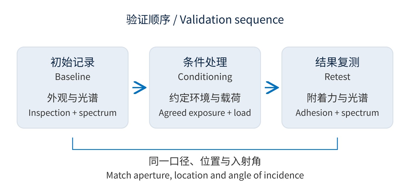
Fig. 2 starts with a baseline and ends with matched measurements. The ECSS peel-and pull-off test method likewise addresses adhesion after relevant environmental exposure. Applicability to a particular filter must be agreed for its materials and construction.
A tape test is a procedural screen, not a direct measurement of $G_{\mathrm{c}}$. Scribing or pull-off tests may require sacrificial specimens. Witness samples should match the substrate and deposition process, but cannot fully reproduce finished edges or mounting loads.
Separate acceptance criteria for the clear aperture and the peripheral region. Record where any lifting begins rather than reducing the result to a single pass mark. If specimens are tested sequentially, document that history: an adhesion test performed after conditioning answers a different question from one performed only on an untreated sample.
Outdoor optics may face moisture entering at exposed edges. Frequently cleaned vision windows also need assessment of wiping loads and solvent compatibility. The shared goal is reliable bonding, but the qualification sequence should follow the actual exposure.
In weak-signal instruments, local separation in narrow bandpass filters can introduce scatter and out-of-band leakage while producing only a small change in aperture-averaged transmission. Microscopy, spatial spectral checks and system stray-light measurements provide complementary evidence.
Mounting can also change the load path. Contact near an exposed coating edge may concentrate force where defects already exist. An optic qualified as a loose component therefore needs an assembly review when a retaining ring or bonded mount is introduced. The useful question is whether the tested configuration represents the intended instrument, rather than whether the coating process has a reassuring name.
Hardness does not guarantee adhesion. Greater thickness can increase stored elastic energy, and an outer protective layer cannot automatically strengthen the substrate interface. Any added layer needs optical and mechanical review.
Likewise, a stable peak transmission value cannot rule out a small detached region. Retesting should retain spatial information wherever possible, especially at edges and mounting contacts, so a local defect is not hidden by an average measurement.
Passing one tape test does not establish a service lifetime. Spectral drift after thermal cycling is not, by itself, proof of delamination either. A defensible assessment combines the fracture location, appearance under specified loads and optical measurements before and after conditioning. Edge lifting should trigger an interface and process investigation before a rework decision.
 365nm Narrow Bandpass Filter | Ø50mm | T>90%
OT-HBP3659050
365nm Narrow Bandpass Filter; FWHM 10nm; transmission >90%; blocking OD5; size Ø50mm; AOI 0°.
 450nm Narrow Bandpass Filter | Ø50mm
OT-HBP4509050
450nm Narrow Bandpass Filter; FWHM 10nm; transmission >90%; blocking OD5; size Ø50mm; AOI 0°.
 525nm Narrow Bandpass Filter | Ø50mm
OT-HBP5259050
525nm Narrow Bandpass Filter; FWHM 10nm; transmission >90%; blocking OD5; size Ø50mm; AOI 0°.
Send us your drawing and spectral targets — an engineer replies with a feasibility check and quotation within one business day.