Original content by the OOTEE Optics editorial team, drawn from first-hand production line and inspection data. Please credit the source when republishing.
Given limits in expertise and test conditions, the theories, parameters and conclusions here carry no guarantee of absolute accuracy. For technical learning and exchange only - never the sole basis for design, acceptance or selection. Corrections welcome.
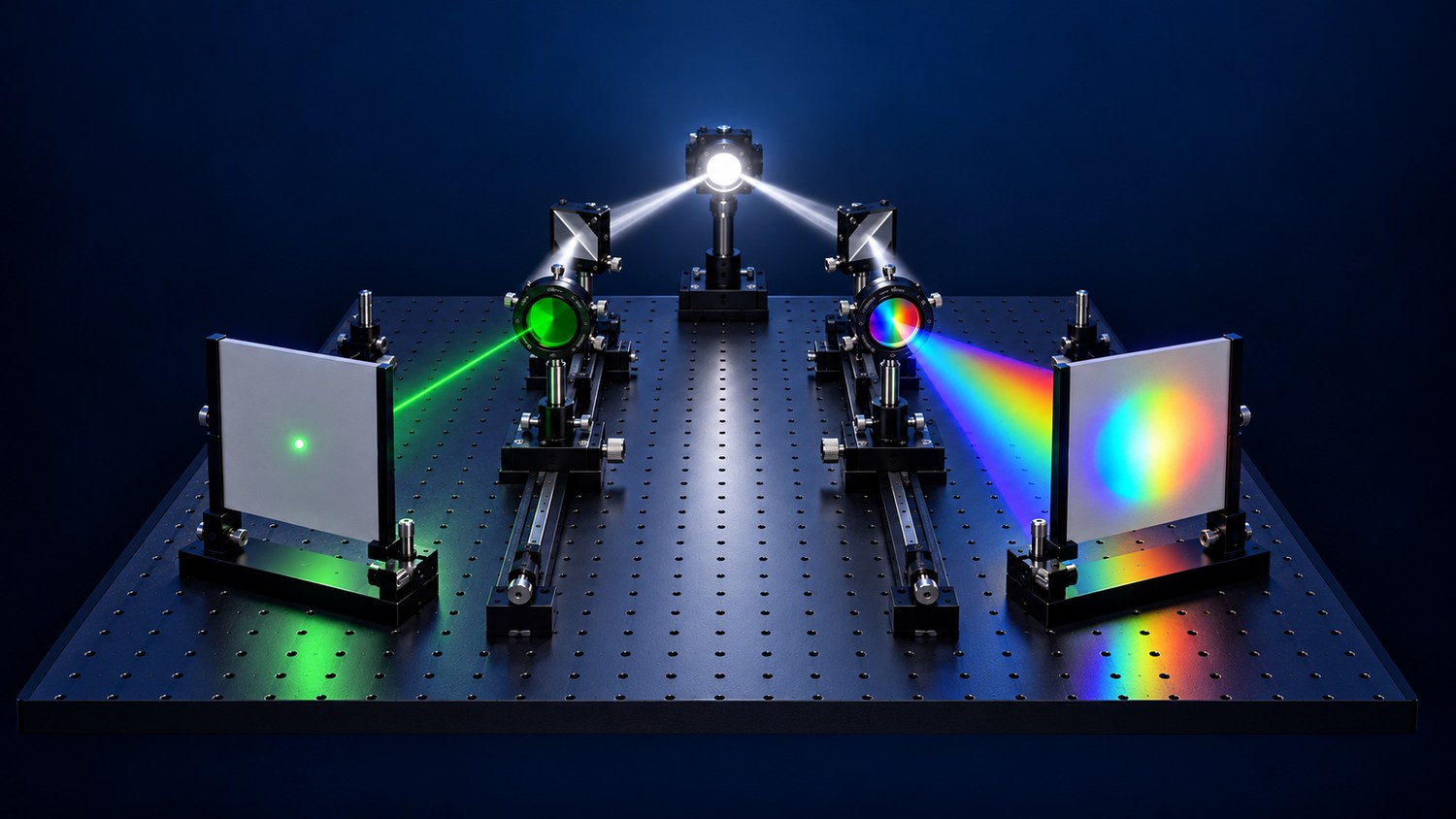
Bandwidth describes the spectral window a filter transmits. It does not specify aperture or beam diameter. There is no universal boundary: in visible systems, a 100 nm window is often considered broad and a 10 nm window narrow. Relative bandwidth also matters when comparing different wavelength regions.
Center wavelength (CWL) locates the window; full width at half maximum (FWHM) measures its width at half peak transmission. The useful question is how much of the target spectrum must reach the detector. All specifications below are examples, not product identifiers.
The cover uses spot area as a visual analogy. Actual spot size depends on imaging, aperture and scattering; it cannot measure spectral bandwidth.
Interference coatings create the transmission window. Optical density (OD) specifies rejection, while angle of incidence (AOI) affects the operating spectrum. A comparison needs the source spectrum and detector response, not just peak transmission.
$$S=\int s(\lambda)T(\lambda)\eta(\lambda)\,\mathrm{d}\lambda,\qquad B=\int b(\lambda)T(\lambda)\eta(\lambda)\,\mathrm{d}\lambda$$
Here, $s$ and $b$ are signal and background photon spectra accumulated during one exposure, $T$ is transmission, and $\eta$ is quantum efficiency. The integrals give electron counts. For a locally flat background and detector response, background increases with equivalent bandwidth. Signal increases only where the target emits.
$$\mathrm{SNR}=\frac{S}{\sqrt{S+B+D+\sigma_{\mathrm{r}}^2}}$$
This model assumes independent Poisson contributions and read noise. $D$ is the dark electron count and $\sigma_{\mathrm{r}}$ the read noise standard deviation. Subtracting background removes its mean, not its shot noise. A separately measured background adds measurement noise of its own.
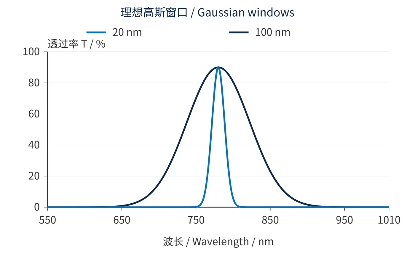
Fig. 1 compares calculated Gaussian windows sharing CWL 780 nm and 90% peak transmission. These illustrative curves do not specify a coating design, edge profile or certified blocking level.
Measure the target spectrum under operating conditions. Define the interval that must pass, then allow for source drift, source variation, filter tolerances and angular shifts. In a converging beam, evaluate the full cone rather than the chief ray alone.
Compare integrated signal and background for each candidate. If both windows preserve nearly all target photons, reducing bandwidth from 100 nm to 20 nm cuts a flat background to approximately one fifth. In the background dominated limit, with everything else unchanged, SNR improves by about $\sqrt{5}$. Losing substantial signal invalidates that shortcut.
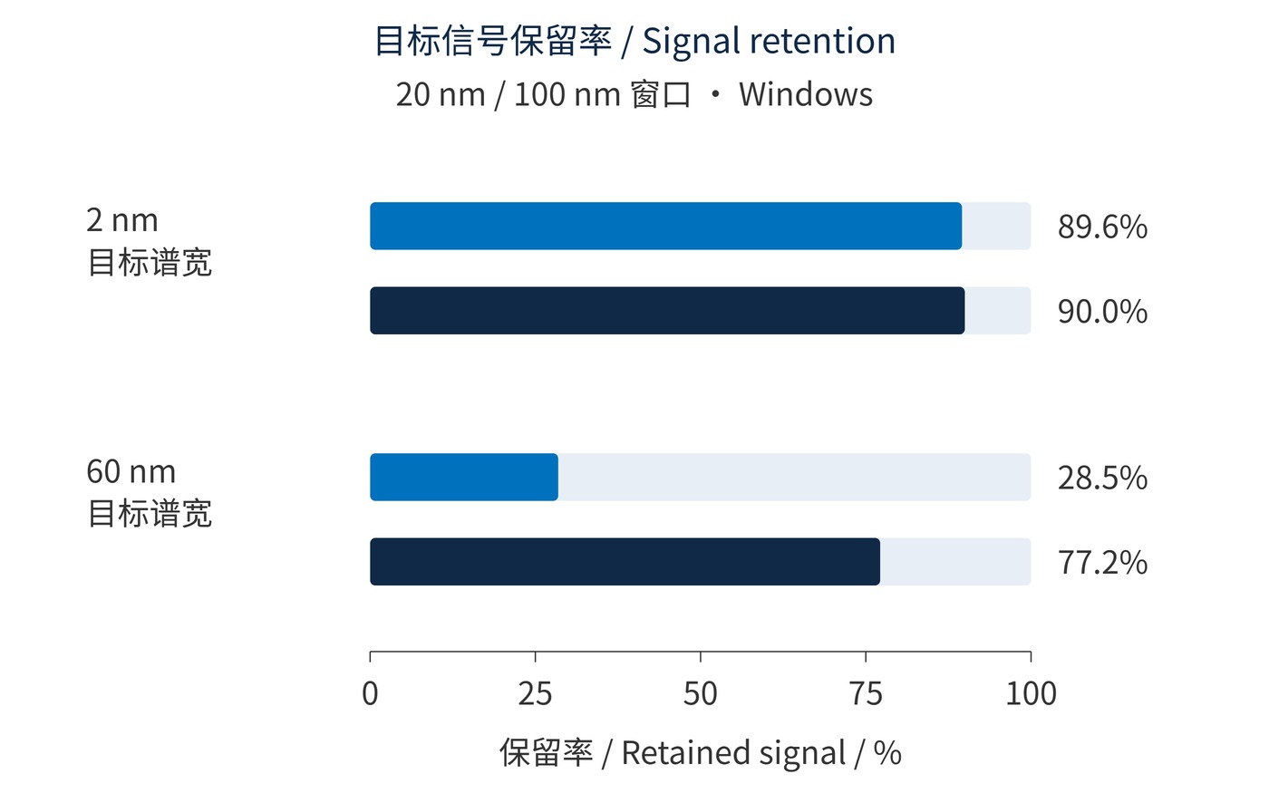
As Fig. 2 shows, a narrow window can discard most of a broad emission spectrum. Broadband collection becomes attractive when exposure cannot increase, read noise dominates, or several spectral regions carry useful information. Optimize SNR alongside exposure time and saturation margin.
The calculation uses Gaussian target spectra centered at 780 nm, with FWHM values of 2 nm and 60 nm, and constant quantum efficiency. Retention includes the filter's transmission loss. For the 2 nm source, both windows retain approximately 90% of the signal. For the 60 nm source, the narrow window retains about 28%, compared with 77% through the broad window. These are illustrative photon budgets, not measured performance. A real source with multiple peaks or an asymmetric emission tail requires integration of its measured spectrum rather than substitution of a nominal linewidth.
| Decision factor | Favors narrowband | Favors broadband |
|---|---|---|
| Useful spectrum | Concentrated spectral line | Distributed emission |
| Main limitation | Background or channel leakage | Photon budget or exposure time |
| Check first | Minimum transmission after drift | Added background and saturation |
Translate the result into acceptance criteria. An example is CWL 780 nm, FWHM 20 nm, minimum transmission 85% over 775–785 nm, and OD6 blocking over 400–750 nm and 810–1100 nm. Specify the intervening transition regions separately, together with AOI, cone angle and temperature. OD6 means transmission no greater than one millionth within the stated blocking ranges.
Active illumination in ambient light benefits from testing a narrow window that covers source drift. A broad source may lose too many photons in that window. Fluorescence collection often needs a wider emission interval while rejecting excitation and neighboring channels; the excitation filter's bandwidth is not automatically appropriate for collection.
Broad spectral intensity measurements and some imaging tasks need more photons or spectral information. Check background, combined spectral response and the detector's long wavelength sensitivity. Compare samples with identical illumination, exposure, gain, temperature and geometry, recording signal, background and repeatability.
Narrower does not guarantee better precision, and broader does not guarantee more detected light. FWHM guarantees neither minimum transmission across the target interval nor rejection far outside it.
Peak transmission and nominal OD are insufficient acceptance criteria. Longer exposure also accumulates background and may cause motion blur or saturation. Confirm the integrated photon budget at the operating angle and temperature, then verify SNR in the complete instrument.
 365nm Narrow Bandpass Filter | Ø50mm | T>90%
OT-HBP3659050
365nm Narrow Bandpass Filter; FWHM 10nm; transmission >90%; blocking OD5; size Ø50mm; AOI 0°.
 450nm Narrow Bandpass Filter | Ø50mm
OT-HBP4509050
450nm Narrow Bandpass Filter; FWHM 10nm; transmission >90%; blocking OD5; size Ø50mm; AOI 0°.
 525nm Narrow Bandpass Filter | Ø50mm
OT-HBP5259050
525nm Narrow Bandpass Filter; FWHM 10nm; transmission >90%; blocking OD5; size Ø50mm; AOI 0°.
Send us your drawing and spectral targets — an engineer replies with a feasibility check and quotation within one business day.



