Original content by the OOTEE Optics editorial team, drawn from first-hand production line and inspection data. Please credit the source when republishing.
Given limits in expertise and test conditions, the theories, parameters and conclusions here carry no guarantee of absolute accuracy. For technical learning and exchange only - never the sole basis for design, acceptance or selection. Corrections welcome.

A cemented filter joins 2 or more optical elements with a transparent optical adhesive. A monolithic filter uses one continuous substrate, with no adhesive joining separate substrates in the clear aperture. “Monolithic” does not mean a single coating layer: one substrate may carry many dielectric layers on either or both faces.
As shown in Fig. 1, the defining feature is the bonded interface, rather than overall thickness. Cementing can combine spectral, absorbing or protective functions. The illustrated coating arrangement is one example; adhesive is not necessarily the wavelength-selective material. Edge sealing should also be distinguished from a full-aperture bond.
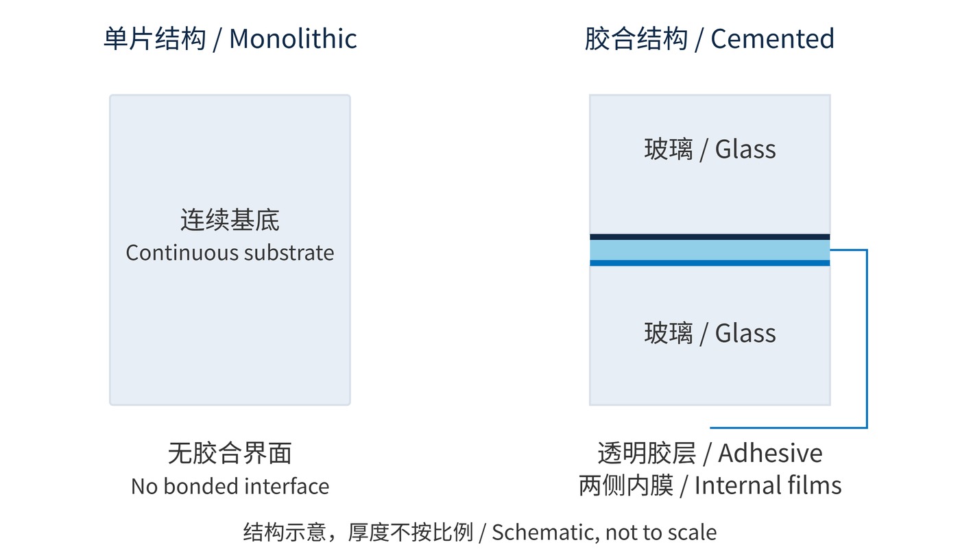
Coating interference and material absorption still determine spectral filtering. Specify center wavelength (CWL), full width at half maximum (FWHM), optical density (OD) and angle of incidence (AOI) for the complete assembly. Measurements of loose elements do not automatically describe the bonded result.
When coherent interference and multiple reflections between elements are negligible, assembly transmission can be approximated by:
$$T_{\mathrm{asm}}(\lambda)\approx T_1(\lambda)T_{\mathrm{g}}(\lambda)T_2(\lambda),\qquad \mathrm{OD}(\lambda)=-\log_{10}T(\lambda)$$
Transmission is a fraction between 0 and 1. Under these assumptions, OD values add at the same wavelength. Transmissions of 0.95, 0.98 and 0.95 yield approximately 88.4% overall. However, bonding changes the refractive-index boundary at a coating, so multiplying air-measured element spectra may give the wrong result.
For a single interface between nonabsorbing media at normal incidence, intensity reflectance is:
$$R=\left(\frac{n_1-n_2}{n_1+n_2}\right)^2$$
Glass with index 1.52 reflects approximately 4.26% at an air interface, versus 0.0044% against adhesive with index 1.50. These are uncoated interface calculations, not assembly predictions. Index matching does not eliminate adhesive absorption, fluorescence, bubbles or curing stress.
A requirement such as CWL 780 nm, FWHM 20 nm and OD6 needs a defined blocking interval, minimum passband transmission, AOI of 0° and beam cone angle. OD6 alone says nothing about suppression throughout the detector response range.
| Check | Cemented assembly | Monolithic element |
|---|---|---|
| Optical path | Adhesive thickness, absorption and fluorescence | Substrate absorption and coating layout |
| Environment | Bond integrity, edge seal and cure | Coating adhesion and substrate stress |
| Installation | Total thickness, parallelism and clear aperture | Surface figure and mounting allowance |
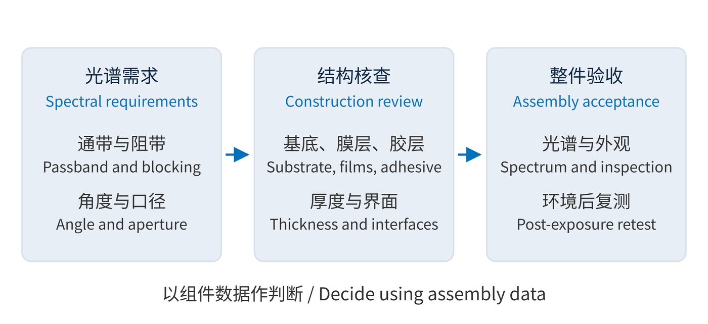
Fig. 2 links the specification to assembly acceptance. Request a section drawing, adhesive wavelength limits and assembled-part results; an adhesive temperature rating alone is insufficient. For narrow bandpass filters, confirm that the bonding medium is included in the coating design and assess transmission across the actual angular distribution.
In fluorescence detection, bonding can combine interference selection with absorbing blocking glass, or enclose a sensitive coating. Measure background using the actual excitation wavelength and detection band: visually clear adhesive does not establish suitability for weak-signal detection.
Machine-vision assemblies may benefit from fewer separately mounted filters, although thickness and parallelism still affect focus and ghosts. A monolithic option for high power, deep ultraviolet or large temperature excursions removes a bonded interface from consideration. Its substrate and coatings still require appropriate power and environmental qualification.
Decide whether integration solves a real packaging problem. A cemented unit can fix the relative placement of its elements, but it also makes those elements difficult to replace independently. Check the drawing for usable aperture, total thickness and the mounting reference face before comparing mechanical compatibility. An unchanged outer diameter does not establish interchangeability.
For an imaging system, evaluate the finished part in the intended beam rather than relying only on a small-area spectrometer scan. Spatially localized bubbles, bond nonuniformity or distortion may matter even when the averaged spectrum passes. For a weak-signal instrument, separate transmitted excitation leakage from light generated inside the assembly: a deeper blocking specification alone does not describe both contributions.
A documented example of enclosing a filtering film between bonded plates appears in the NIST report on metal-on-quartz reference filters. That arrangement illustrates one construction, rather than a universal prescription for adhesive choice or coating placement.
 365nm Narrow Bandpass Filter | Ø50mm | T>90%
OT-HBP3659050
365nm Narrow Bandpass Filter; FWHM 10nm; transmission >90%; blocking OD5; size Ø50mm; AOI 0°.
 450nm Narrow Bandpass Filter | Ø50mm
OT-HBP4509050
450nm Narrow Bandpass Filter; FWHM 10nm; transmission >90%; blocking OD5; size Ø50mm; AOI 0°.
 525nm Narrow Bandpass Filter | Ø50mm
OT-HBP5259050
525nm Narrow Bandpass Filter; FWHM 10nm; transmission >90%; blocking OD5; size Ø50mm; AOI 0°.
Send us your drawing and spectral targets — an engineer replies with a feasibility check and quotation within one business day.