Original content by the OOTEE Optics editorial team, drawn from first-hand production line and inspection data. Please credit the source when republishing.
Given limits in expertise and test conditions, the theories, parameters and conclusions here carry no guarantee of absolute accuracy. For technical learning and exchange only - never the sole basis for design, acceptance or selection. Corrections welcome.
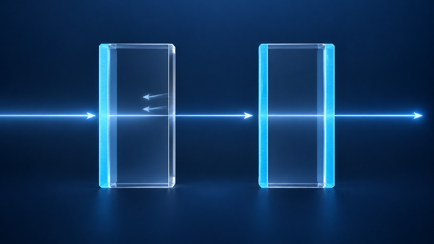
A single-sided coating places a functional film stack on one optical surface of a substrate. A double-sided coating uses both surfaces. Either surface can carry many individual layers: “double-sided” describes where the stacks are deposited, not their layer count or performance grade.
A common arrangement combines wavelength selection on the front with an antireflection (AR) coating on the rear. Alternatively, the two surfaces can share spectral blocking duties. Fig. 1 distinguishes a bare rear surface from an AR-treated one. Film thickness is exaggerated; the arrows describe paths rather than measured intensities.
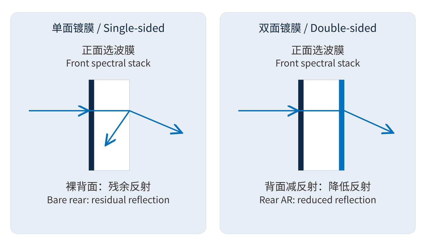
An uncoated glass–air boundary still reflects light. For a lossless bare interface at normal incidence:
$$R=\left(\frac{n_{\mathrm{s}}-n_0}{n_{\mathrm{s}}+n_0}\right)^2$$
With a glass index of 1.52 and an air index of 1, reflectance is approximately 4.26%. Suppose the front stack transmits 98% in the passband. Ignoring substrate absorption and recovered multiple reflections, direct transmission is about 93.8% with a bare rear face, versus 97.5% if rear reflectance is reduced to 0.5%. These are illustrative assumptions, not specifications for a supplied filter.
Defining interface transmission in the actual propagation direction gives the direct-beam estimate:
$$T_{\mathrm{direct}}\approx T_{\mathrm{front}}\,\tau_{\mathrm{sub}}\,T_{\mathrm{back}}$$
Here, $\tau_{\mathrm{sub}}$ excludes surface losses. This budget omits repeated round trips. Coherent illumination through parallel surfaces can produce interference fringes requiring a more complete model. AR performance is also limited to its specified wavelength, angle and polarization range.
Specify center wavelength (CWL), full width at half maximum (FWHM), and optical density (OD) for the finished optic. Define angle of incidence (AOI) as the external angle in air when that is the intended condition. Optical density is:
$$\mathrm{OD}(\lambda)=-\log_{10}T(\lambda)$$
OD6 means transmission of $10^{-6}$, or 0.0001%. OD values add only when transmissions multiply at the same wavelength and bypass light, scatter and multiple-reflection coupling are negligible. Two surface-level OD claims do not establish the finished filter’s blocking.
For a narrow bandpass filter, an example requirement is CWL 780 nm, FWHM 20 nm, peak transmission ≥95%, and OD6 blocking over 400–740 nm and 820–1100 nm at AOI 0°. Transition regions within 740–820 nm need separate limits. Measurement resolution, temperature and clear aperture must also be agreed.
| Constraint | Possible arrangement | Acceptance focus |
|---|---|---|
| Tight passband loss budget | Spectral front stack, rear AR | Finished transmission and rear reflectance |
| Extended blocking range | Complementary blocking stacks | OD throughout every specified interval |
| Reflection is the useful output | Prioritize the incident-side stack | Useful reflectance and rear-surface ghosts |
| Mounting or figure is critical | Compare complete coating processes | Post-coating figure, orientation and clamping zone |
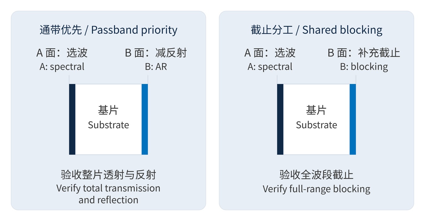
Fig. 2 shows why the rear coating needs a functional description. Identify surfaces A and B and the intended incident direction on the drawing. Processing a second face adds handling, cleaning and fixturing. Balanced coatings can sometimes reduce bending, but the result depends on thickness and stress, as discussed in film stress and crazing.
Keep component acceptance separate from system acceptance. A transmission measurement can confirm the specified passband while missing a troublesome ghost in the assembled instrument. Likewise, an isolated rear-surface reflectance value does not establish complete-filter blocking. Ask for the spectral measurement geometry and the detector’s usable dynamic range when assessing OD6 data. For a mounted optic, confirm that the tested clear aperture matches the illuminated region and that clamping does not introduce a figure change large enough to affect the application.
In weak-signal imaging, rear AR can improve throughput and reduce ghosts caused by reflections between the filter and detector. The benefit depends on detector reflectance, spacing and beam geometry. Fluorescence systems additionally require finished-optic blocking at excitation wavelengths and adequate emission transmission; counting coated faces cannot predict background.
For dichroic mirrors, the incident-side stack performs the main spectral separation. Rear AR can reduce unwanted reflections in the transmitted branch. At AOI 45°, both stacks need the relevant angular and polarization specifications. Normal-incidence AR data are insufficient. Laser systems also require return-light and damage-threshold checks under the intended pulse conditions.
Judge the completed optic by its spectrum, reflections and figure under the specified operating and mounting conditions.
 365nm Narrow Bandpass Filter | Ø50mm | T>90%
OT-HBP3659050
365nm Narrow Bandpass Filter; FWHM 10nm; transmission >90%; blocking OD5; size Ø50mm; AOI 0°.
 450nm Narrow Bandpass Filter | Ø50mm
OT-HBP4509050
450nm Narrow Bandpass Filter; FWHM 10nm; transmission >90%; blocking OD5; size Ø50mm; AOI 0°.
 525nm Narrow Bandpass Filter | Ø50mm
OT-HBP5259050
525nm Narrow Bandpass Filter; FWHM 10nm; transmission >90%; blocking OD5; size Ø50mm; AOI 0°.
Send us your drawing and spectral targets — an engineer replies with a feasibility check and quotation within one business day.