Original content by the OOTEE Optics editorial team, drawn from first-hand production line and inspection data. Please credit the source when republishing.
Given limits in expertise and test conditions, the theories, parameters and conclusions here carry no guarantee of absolute accuracy. For technical learning and exchange only - never the sole basis for design, acceptance or selection. Corrections welcome.
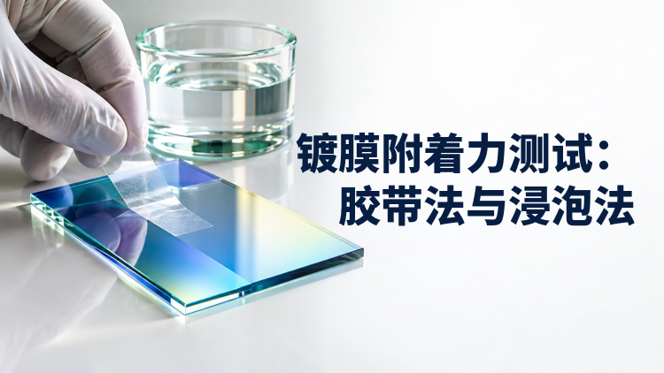
Adhesion testing asks whether a coating detaches from its substrate or separates between layers under a defined challenge. Tape introduces a peeling load. Immersion exposes the coating, interfaces and edges to water, sometimes with heat. Neither method delivers a bond strength in MPa or a service-life prediction.
Adhesion, abrasion resistance and water resistance require separate acceptance criteria. ISO 9211-4:2022 addresses these tests for optical coatings. Specify the edition, applicable procedure and severity before testing; the article below is a planning guide rather than a substitute for the selected procedure.
Tape chemistry, width, age, application pressure, dwell, peel speed and angle all influence the result. Fig. 1 distinguishes 90° from 180° peeling. ASTM D3359-23 calls for rapid removal back upon itself near 180°. Its scope and cut-pattern ratings should not be transferred directly to precision optical films.
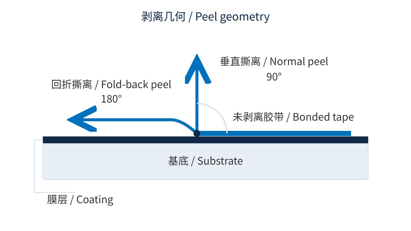
For an ideal flexible, inextensible tape in steady peeling, the following relation illustrates the angle effect. Here $F$ is force, $b$ is tape width and $G$ is energy released per unit area.
$$G \approx \frac{F}{b}(1-\cos\theta)$$
Real adhesive deformation and tape stretching consume energy, and the fracture may follow a different interface. The equation therefore cannot turn a tape result into coating bond strength. Immersion introduces water uptake, leaching or interface weakening; boiling adds thermal stress. Record water quality, measured temperature, duration, immersion depth, edge condition and cooling procedure.
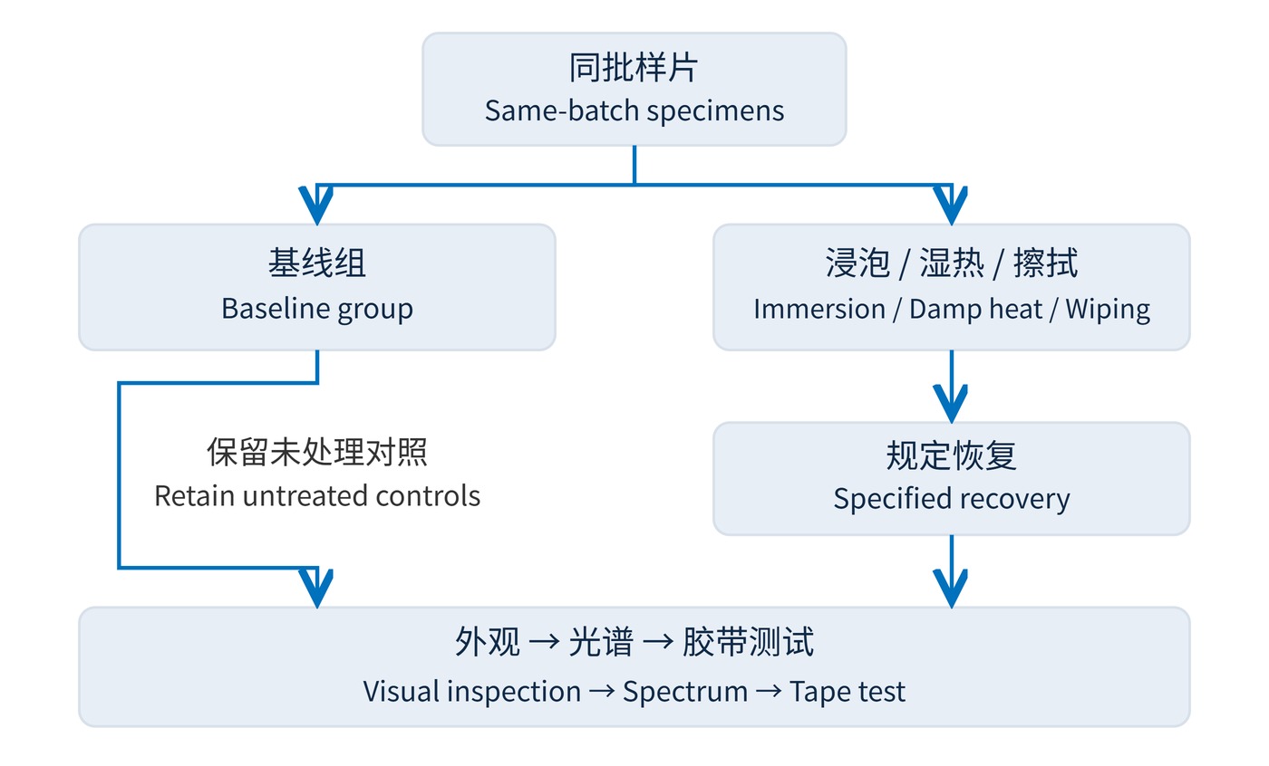
Fig. 2 separates baseline and conditioned groups from the same batch. Possible screening conditions for discussion include deionized water at 23 °C for 24 h, or 1 h at the local boiling point. These are negotiated examples, not standard defaults or universal acceptance limits. Check compatibility first for cemented parts, water-sensitive substrates and sealed assemblies.
| Observation | Evidence to examine | Decision |
|---|---|---|
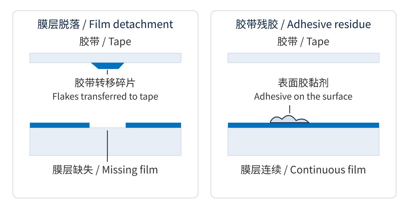
| Flaking, lifting or missing film | Match the missing area to material transferred onto tape | Fail a no-detachment requirement within the specified area |
| Sticky marks or haze | Possible adhesive residue; colour alone is inconclusive | Preserve evidence and investigate with a validated method |
| Spectral change without detachment | Consider moisture, contamination and coating changes | Apply separate optical acceptance limits |
As Fig. 3 shows, compare corresponding locations on the optic and tape before cleaning. Wiping too early can destroy evidence. Suspected residue is not an automatic pass: isolate ambiguous samples and use microscopy or surface analysis when needed.
Photograph both surfaces under consistent illumination and magnification. A bright patch alone does not establish which material has been removed. Keep the inspection area and any permitted edge exclusions explicit in the report. Where a no-detachment criterion applies, confirmed lifting or flaking inside that area fails the requirement even if average transmission remains acceptable.
Frequently cleaned vision windows may need retesting after wiping with a defined medium, load and cycle count. Humid installations may require damp-heat exposure followed by recovery and tape testing. Keep untreated controls and separate exposure groups: sequence changes the challenge. Set the protocol alongside the relevant coating durability requirements.
For a narrow bandpass filter with center wavelength (CWL) 780 nm, full width at half maximum (FWHM) 20 nm and blocking optical density (OD) 6, inspect both passband and blocking performance. Match angle of incidence (AOI), polarization, beam footprint and measurement temperature before and after exposure.
$$\Delta T_{\mathrm{pp}}(\lambda)=100\,[T_{\mathrm{after}}(\lambda)-T_{\mathrm{before}}(\lambda)]$$
With $T$ expressed from 0 to 1, the result is in percentage points: 0.95 to 0.94 is a decrease of 1 percentage point. Agree limits across the operating spectrum. Verifying OD6 also requires adequate instrument dynamic range and stray-light control.
A stronger adhesive does not automatically make a more informative test; the tape itself can fail. Applying tape to a wet surface can produce weak contact and a misleading pass. Record wet-state observations separately from adhesion results after the prescribed drying and recovery period. A change in recovery time can alter the outcome, so repeat tests must follow the same timing rather than wait until a specimen looks dry.
Boiling does not reproduce damp heat, salt exposure, solvents, ultraviolet radiation or laser loading. Bare-part immersion also misses condensation and seal failures inside a mount. Without a shared failure mechanism and field correlation, 1 h in boiling water cannot be converted into years of operation. Report whether the sampled batch met the specified adhesion and optical criteria under the documented conditions.
 365nm Narrow Bandpass Filter | Ø50mm | T>90%
OT-HBP3659050
365nm Narrow Bandpass Filter; FWHM 10nm; transmission >90%; blocking OD5; size Ø50mm; AOI 0°.
 450nm Narrow Bandpass Filter | Ø50mm
OT-HBP4509050
450nm Narrow Bandpass Filter; FWHM 10nm; transmission >90%; blocking OD5; size Ø50mm; AOI 0°.
 525nm Narrow Bandpass Filter | Ø50mm
OT-HBP5259050
525nm Narrow Bandpass Filter; FWHM 10nm; transmission >90%; blocking OD5; size Ø50mm; AOI 0°.
Send us your drawing and spectral targets — an engineer replies with a feasibility check and quotation within one business day.



