Original content by the OOTEE Optics editorial team, drawn from first-hand production line and inspection data. Please credit the source when republishing.
Given limits in expertise and test conditions, the theories, parameters and conclusions here carry no guarantee of absolute accuracy. For technical learning and exchange only - never the sole basis for design, acceptance or selection. Corrections welcome.
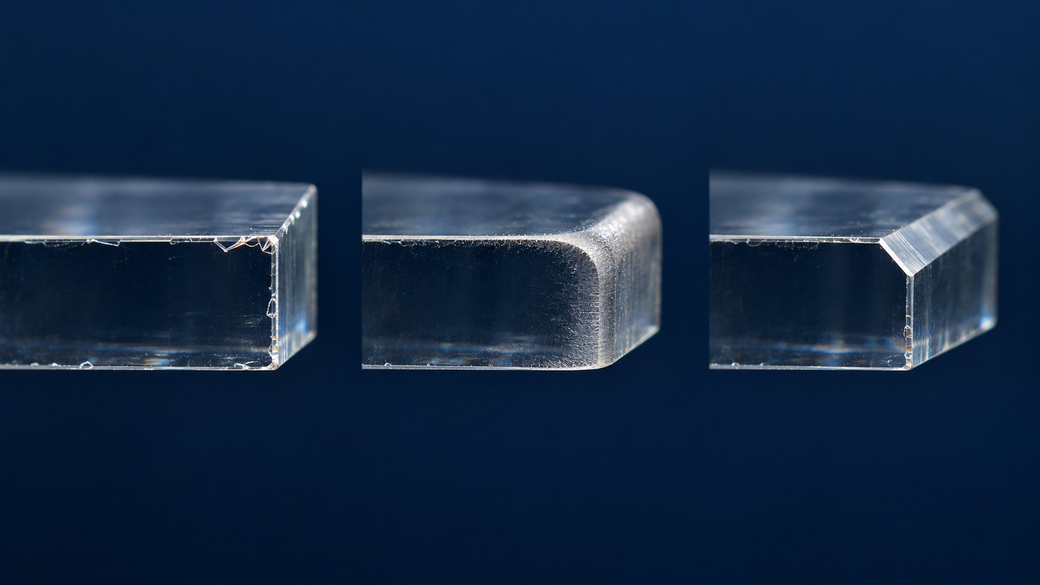
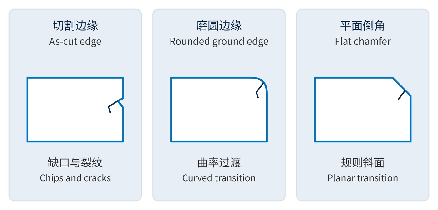
Cutting separates a blank; edging establishes its final boundary and removes damaged material; chamfering replaces a sharp face-to-side intersection with a controlled facet. A rounded edge is a different geometry from a flat chamfer. “Edges finished” therefore leaves too much open to interpretation.
Useful acceptance criteria distinguish chips, cracks, machining texture and transition geometry. In brittle glass, an apparent burr is usually a small fragment or notch rather than plastically displaced material. Fig. 1 compares edge profiles and shows why a tidy outline does not establish freedom from subsurface damage. The issue is how defects survive successive operations.
Scribe-and-break separation propagates a crack; diamond sawing removes material through abrasive action. Both can leave chipped regions and cracks. Subsequent grinding must remove the inherited damage without introducing unacceptable new damage. Abrasive load, wheel condition, feed and cooling all matter. Unsupported tool exit during chamfering can create another chip.
A linear-elastic fracture-mechanics screening model relates a tensile load to an existing crack:
$$K_{\mathrm{I}}=Y\sigma\sqrt{\pi a}$$
Here $a$ is crack depth, $\sigma$ is local tensile stress and $Y$ depends on crack and loading geometry. Instability becomes possible when $K_{\mathrm{I}}$ reaches fracture toughness $K_{\mathrm{IC}}$. This is not a lifetime prediction: humidity, sustained loading and flaw populations also require assessment, a point also made throughout Corning’s published glass reliability work.
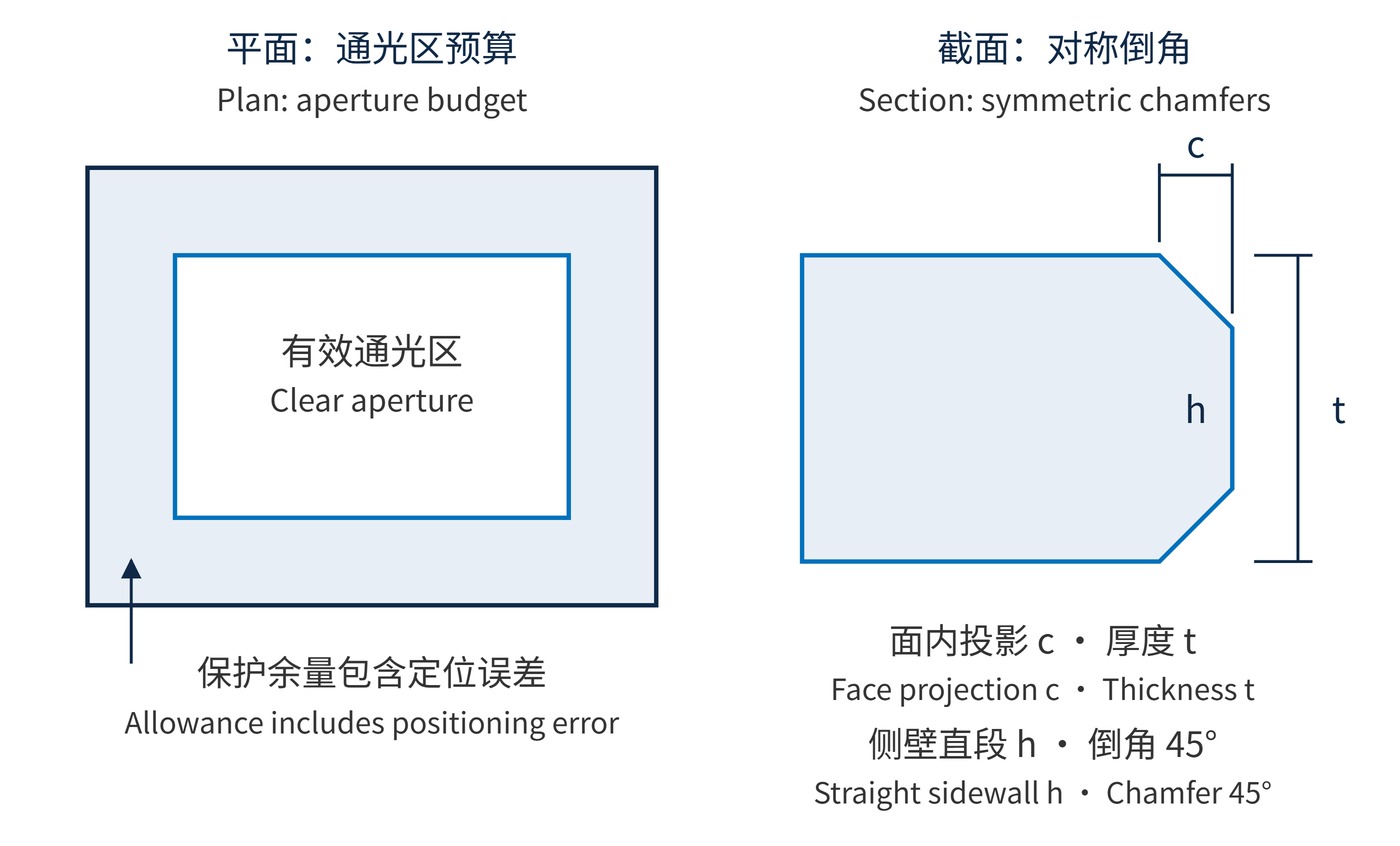
Drawings should distinguish facet width from its projection onto the optical face. For matching 45° chamfers on both faces, each with projected width $c$, the remaining straight sidewall height is:
$$h=t-2c,\qquad \theta=45^{\circ}$$
A thickness $t=1.00\,\mathrm{mm}$ and projection $c=0.10\,\mathrm{mm}$ leave $h=0.80\,\mathrm{mm}$. The projection is not the facet width. This relationship assumes a symmetric section and does not describe a rounded edge. Likewise, grinding stock should be based on damage-depth evidence from trials, rather than visible chip size alone.
Start with substrate, thickness, clear aperture and mounting conditions. As Fig. 2 shows, the edge allowance must accommodate the chamfer, permitted defects and positioning uncertainty. These are dimensional budgets, not coating boundaries.
| Item | Illustrative agreement, not a general standard | Inspection requirement |
|---|---|---|
| Geometry | Thickness 1.00 mm; projection 0.10 ± 0.03 mm; angle 45° ± 5° | Measure both faces, all edges and corners |
| Chips | Face intrusion ≤0.05 mm; none within the clear aperture | Define the reference edge or facet intersection |
| Cracks | No visible cracks under agreed conditions | Record illumination, magnification and detection limit |
| Cleanliness | No visible loose particles after cleaning | Inspect after drying and prevent handling damage |
Reassess these example values for thin parts, small apertures and different materials. First-article microscopy should include every edge, corner and face intersection. Visual inspection cannot certify zero subsurface damage; sectioned witness samples or destructive strength tests may be necessary.
For a repeatable inspection, keep the same illumination direction and inspect both face intersections as well as the sidewall. Record the measurement reference before judging a chip: distance from the original outer boundary and distance from the chamfer intersection describe different quantities. Check corners individually rather than assuming that a satisfactory straight edge represents the entire perimeter.
Specify the sequence relative to coating, too. Machining an already coated part can damage the coating termination; machining first introduces later fixturing and masking considerations. Edge cracks can coexist with coating stress and crazing. Their locations and propagation directions help separate the failure mechanisms.
For compact machine vision filters, match the chamfer to the seat relief and apply retaining force within the intended support region. Loading directly onto a facet can produce line contact. Thin substrates particularly need uniform support and controlled preload; a larger chamfer cannot compensate for excessive mounting stress.
Weak-signal instruments also need particle and stray-light checks. A filter meeting center wavelength (CWL) 780 nm, full width at half maximum (FWHM) 20 nm, optical density (OD) 6 and angle of incidence (AOI) 0° can still admit unwanted light around an exposed edge. These are illustrative spectral requirements, not a product specification. Check background with the actual beam and holder.
Keep spectral acceptance separate from mechanical acceptance. A transmission measurement through the central aperture does not exercise the edge under retaining force. Conversely, passing an edge inspection does not establish the specified blocking performance. The assembled instrument needs both checks under its intended conditions.
 365nm Narrow Bandpass Filter | Ø50mm | T>90%
OT-HBP3659050
365nm Narrow Bandpass Filter; FWHM 10nm; transmission >90%; blocking OD5; size Ø50mm; AOI 0°.
 450nm Narrow Bandpass Filter | Ø50mm
OT-HBP4509050
450nm Narrow Bandpass Filter; FWHM 10nm; transmission >90%; blocking OD5; size Ø50mm; AOI 0°.
 525nm Narrow Bandpass Filter | Ø50mm
OT-HBP5259050
525nm Narrow Bandpass Filter; FWHM 10nm; transmission >90%; blocking OD5; size Ø50mm; AOI 0°.
Send us your drawing and spectral targets — an engineer replies with a feasibility check and quotation within one business day.