Original content by the OOTEE Optics editorial team, drawn from first-hand production line and inspection data. Please credit the source when republishing.
Given limits in expertise and test conditions, the theories, parameters and conclusions here carry no guarantee of absolute accuracy. For technical learning and exchange only - never the sole basis for design, acceptance or selection. Corrections welcome.
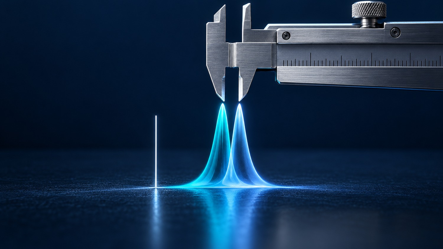
A center wavelength (CWL) tolerance defines the permitted location of a filter passband under agreed measurement conditions. A specification of 780 nm ±1 nm accepts centers from 779 to 781 nm; ±0.5 nm narrows that interval to 779.5–780.5 nm. Neither figure describes source linewidth or instrument resolution.
Agree on the center calculation first. Here, CWL is the midpoint of the two half-maximum crossings, and full width at half maximum (FWHM) is their separation. For an asymmetric passband, the peak wavelength and spectral centroid may give different answers.
$$\lambda_{\mathrm{CWL}}=\frac{\lambda_1+\lambda_2}{2},\qquad \mathrm{FWHM}=\lambda_2-\lambda_1$$
The crossings satisfy $T(\lambda_{1,2})=T_{\mathrm{peak}}/2$. Two individually compliant ±0.5 nm filters can be 1 nm apart. With ±1 nm parts, the extreme separation is 2 nm. Matched channels therefore need a separate relative-center requirement.
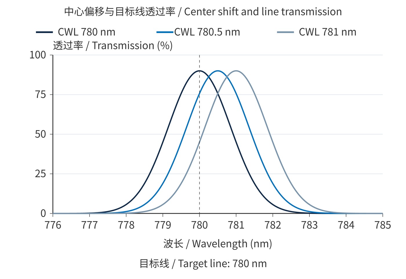
For a narrow fixed source, transmission at the source wavelength matters more than the nominal center alone. Fig. 1 uses a Gaussian passband with 90% peak transmission and 2 nm FWHM. Moving its center by 0.5 nm reduces transmission at 780 nm to about 75.7%; a 1 nm offset gives 45%. These are model results, not measured coating performance.
$$\frac{T(\lambda_{\mathrm{s}})}{T_{\mathrm{peak}}}=\exp\!\left[-4\ln 2\left(\frac{\lambda_{\mathrm{s}}-\lambda_{\mathrm{CWL}}}{B}\right)^2\right]$$
Here $B=\mathrm{FWHM}$. Keeping at least 90% of peak transmission permits an offset of approximately $0.195B$: 0.39 nm for a 2 nm passband, versus 3.90 nm for a 20 nm passband. A flat-top filter needs an allowance derived from its actual edges.
Optical density (OD) is a separate blocking constraint. CWL 780 nm, FWHM 2 nm and OD6 over 800–900 nm still leave transmission at 780 nm unspecified. Include a minimum transmission at the working line.
Start with the maximum mismatch the signal budget permits. Reserve allowances for source variation and residual shifts caused by temperature and angle of incidence (AOI). When extreme combinations must be covered and correlations are unknown, a conservative bound is:
$$E_{\mathrm{fab}}+E_{\mathrm{src}}+E_{\mathrm{use}}\leq D_{\mathrm{allow}}$$
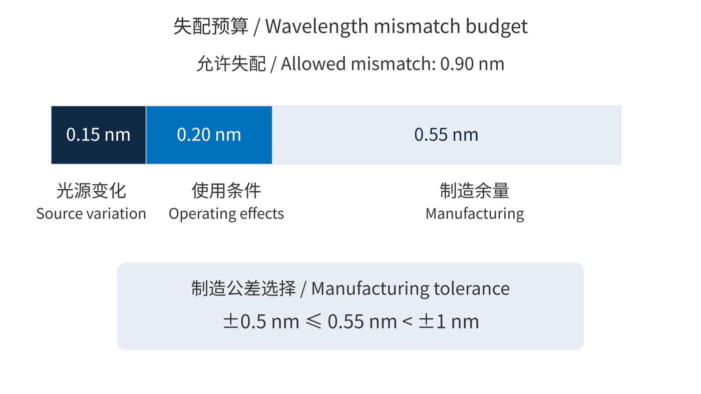
All terms are in nm. The use allowance covers temperature and angle effects; count residual errors after any compensation. In the illustrative budget in Fig. 2, a 0.90 nm total allowance minus 0.15 nm for the source and 0.20 nm for operating conditions leaves 0.55 nm for manufacturing. ±0.5 nm fits; ±1 nm does not.
When reviewing narrow bandpass filters, compare passband shape and minimum line transmission alongside CWL tolerance. A generous budget can justify ±1 nm. A demanding one may require more than tightening the filter to ±0.5 nm: source stabilization or a bandwidth change may also be necessary.
| Acceptance item | What to specify |
|---|---|
| Center and conditions | 780 nm ±0.5 nm; half-maximum midpoint; 23 °C, AOI 0°, collimated beam |
| Spatial sampling | Clear aperture, beam size, center and edge measurement positions |
| Spectral measurement | Wavelength calibration, spectral bandwidth, sampling interval and expanded uncertainty |
| Functional limits | Minimum transmission at 780 nm and blocking OD over a defined range |
A fine sampling interval does not establish wavelength accuracy. One conservative acceptance rule requires the absolute measured offset plus expanded uncertainty to remain within tolerance. An offset of 0.42 nm with 0.10 nm uncertainty would fail that rule for ±0.5 nm. Agree on the rule and retest procedure before delivery.
State the coverage factor with expanded uncertainty. Uncertainty describes confidence in the measurement; it is not automatically another physical wavelength drift to add to the operating budget. For lot sampling, define the sampling fraction and traceability expectations. Passing sampled parts does not establish that every filter has been measured.
Request both tolerance options against the same functional specification. Ask how each will be screened and measured, then choose using the remaining system margin. Tightening CWL alone cannot correct an inadequate minimum transmission or a passband that is too narrow for the source envelope.
Fixed laser-line detection is sensitive to offsets when the filter must also cover laser production spread and thermal drift. Broad fluorescence measurements require a spectral overlap calculation including source emission, filter transmission and detector response.
Evaluate the extremes of the intended operating range rather than only the room-temperature nominal point. If the source and filter shifts track each other, a validated relative-shift model can reduce conservatism. Without that evidence, assume their effects can combine unfavorably. Record whether the specification applies to one measurement spot or the entire illuminated aperture.
Ratio measurements across channels may need tighter matching than individual tolerances provide. If tilt is used for correction, check polarization and bandwidth as well; the effect of incidence angle can change performance while moving the center.
A ±0.5 nm center tolerance says nothing about FWHM tolerance or uniformity across the clear aperture. A compliant center spot does not establish suitability for a large beam.
Do not combine worst-case bounds by root-sum-square without justified distributions, independence and confidence levels. Use one wavelength budget for manufacturing, measurement decisions and operating conditions, then verify the working-line or integrated-signal requirement.
 365nm Narrow Bandpass Filter | Ø50mm | T>90%
OT-HBP3659050
365nm Narrow Bandpass Filter; FWHM 10nm; transmission >90%; blocking OD5; size Ø50mm; AOI 0°.
 450nm Narrow Bandpass Filter | Ø50mm
OT-HBP4509050
450nm Narrow Bandpass Filter; FWHM 10nm; transmission >90%; blocking OD5; size Ø50mm; AOI 0°.
 525nm Narrow Bandpass Filter | Ø50mm
OT-HBP5259050
525nm Narrow Bandpass Filter; FWHM 10nm; transmission >90%; blocking OD5; size Ø50mm; AOI 0°.
Send us your drawing and spectral targets — an engineer replies with a feasibility check and quotation within one business day.



