Original content by the OOTEE Optics editorial team, drawn from first-hand production line and inspection data. Please credit the source when republishing.
Given limits in expertise and test conditions, the theories, parameters and conclusions here carry no guarantee of absolute accuracy. For technical learning and exchange only - never the sole basis for design, acceptance or selection. Corrections welcome.
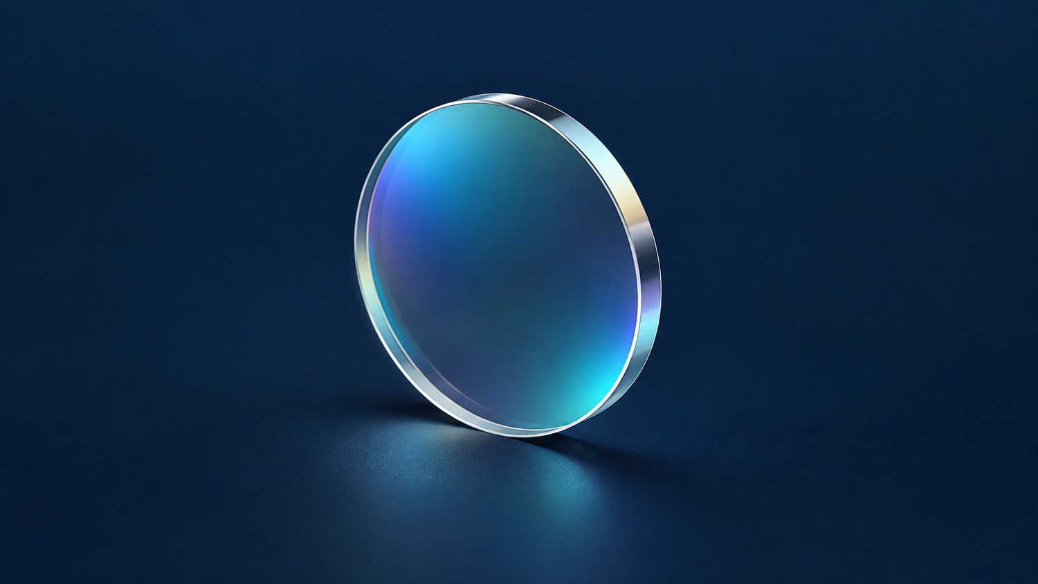
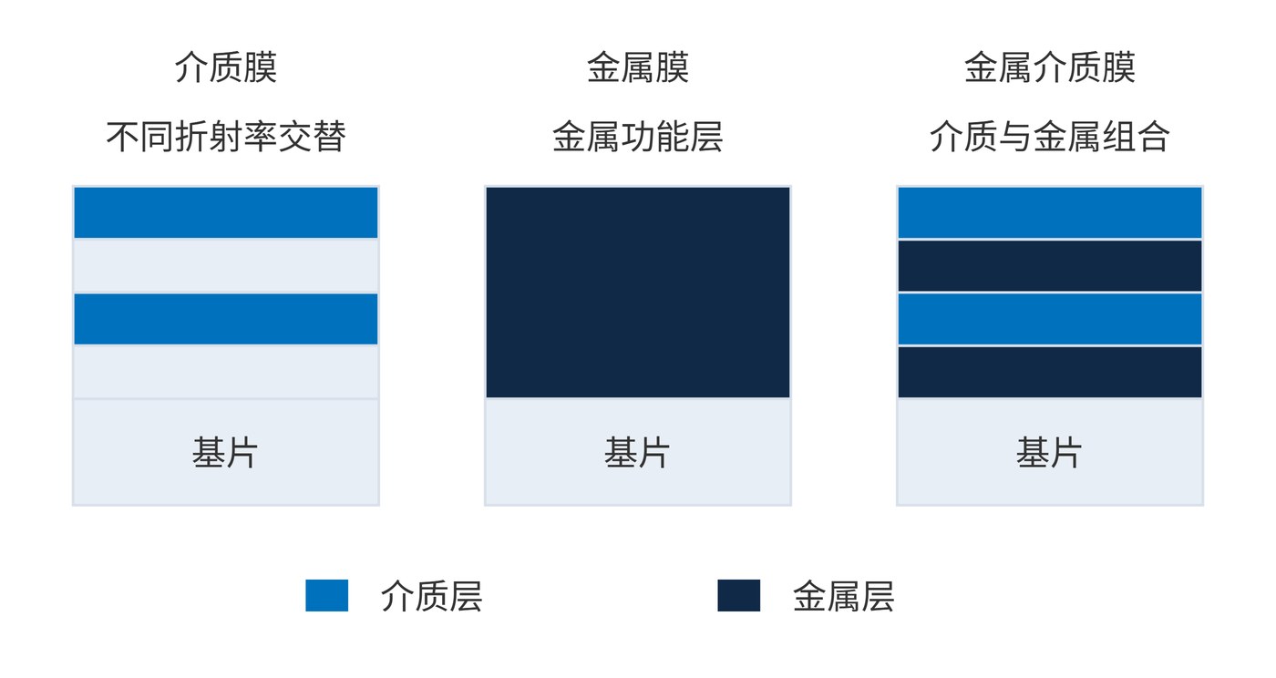
Dielectric, metal and metal-dielectric describe the materials responsible for a coating’s optical response. They do not identify a deposition process or specify whether a coating is mechanically hard. A process name alone cannot tell a buyer how the finished optic divides incident power.
A dielectric coating uses materials with low absorption in the operating band, arranging their refractive indices and thicknesses to control interference. A metal coating provides reflection and absorption; a sufficiently thin layer also transmits light. A metal-dielectric coating combines these mechanisms, using dielectric layers to modify phase and the field around a metal layer.
Fig. 1 shows functional examples, not mandatory recipes. Commercial metal mirrors often include dielectric protection, so the categories overlap. Ask whether those layers merely protect the surface or deliberately shape the spectrum, and whether the metal is opaque or partially transmitting.
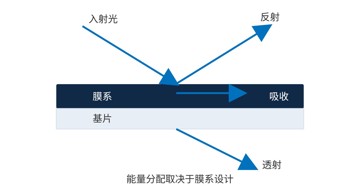
Let $T$, $R$ and $A$ denote transmittance, reflectance and absorptance. Neglecting scattering and collecting all outgoing light, the energy balance is:
$$T(\lambda)+R(\lambda)+A(\lambda)=1$$
Transparent dielectric materials allow spectral selection with low absorption. Metals have a complex refractive index and convert part of the incident power into heat. Hybrid designs redistribute the optical field, potentially enhancing reflection or creating transmission windows. They do not inherently remove metal absorption. Fig. 2 illustrates why a transmission measurement alone cannot establish thermal loading.
Optical density (OD) quantifies transmitted leakage. Use a fractional value for $T$, not a percentage:
$$\mathrm{OD}(\lambda)=-\log_{10}T(\lambda)$$
OD6 therefore means $T=10^{-6}$, or 0.0001%. Heat requires a separate calculation: 10 W incident power and 5% measured absorptance produce 0.5 W of absorbed power. This is an arithmetic example, not a typical value for any coating family.
For wavelength selection, specify center wavelength (CWL), full width at half maximum (FWHM) and angle of incidence (AOI). Dielectric interference changes with optical path length at oblique incidence. Metals also respond to angle and polarization; a hybrid is not automatically more tolerant.
Start with the optical task: selective transmission, reflective beam routing or broadband attenuation. The comparison below identifies questions to investigate, rather than guaranteed performance rankings.
| Coating | Tasks worth evaluating | Tradeoffs to verify |
|---|---|---|
| Dielectric | High throughput, selective splitting, low absorption reflection | Angular cone, polarization and unwanted transmission bands |
| Metal | Broadband reflection, partial transmission, attenuation | Heating, spectral flatness and surface protection |
| Metal-dielectric | Broad response with targeted spectral shaping | Transmission loss, metal absorption and interface reliability |
An example transmission specification is CWL 780 nm, FWHM 20 nm, peak transmittance ≥85%, and OD ≥6 throughout 400–740 nm and 820–1100 nm, at AOI 0° with a beam half-cone angle ≤2°. These are evaluation targets, not a product claim. Require candidate designs to demonstrate the complete spectral envelope.
For broadband attenuation, a requirement such as OD 1.0 ±0.1 over 450–900 nm is more useful than a single value at 780 nm. For a mirror, define minimum reflectance at 45° for S and P polarization, then specify allowable absorbed power, cooling conditions and backside reflections.
Align measurement conditions too: illuminated aperture, wavelength resolution, stray-light floor and sample orientation. High OD calls for adequate measurement dynamic range. Transmission data alone cannot establish a metal layer’s heat load.
For a useful supplier comparison, keep the substrate, working band and illumination geometry consistent. If one proposal assumes a collimated beam and another assumes a converging cone, their headline values describe different tests. Also distinguish a protected metal surface from a multilayer enhancement design: both contain dielectric material, but only the latter is necessarily intended to reshape reflectance through interference. Request the optical function of each layer group rather than treating a proprietary stack description as an acceptance specification. Acceptance should remain tied to measurable behavior.
Weak fluorescence detection prioritizes signal throughput and excitation rejection, making low absorption dielectric filters a useful starting point. Broadband beam folds may favor metal mirrors, provided their spectral coverage, cumulative reflection losses and thermal loading are acceptable.
Power-monitor pickoffs, detector attenuation and transmission filters requiring broad blocking can justify evaluating thin metal or hybrid structures. Their benefit is another way to distribute energy and shape spectra. Assess the resulting signal budget using the source spectrum, filter transmission and detector response together.
The trade-offs above summarise the three families; coating process and acceptance are covered separately.
 365nm Narrow Bandpass Filter | Ø50mm | T>90%
OT-HBP3659050
365nm Narrow Bandpass Filter; FWHM 10nm; transmission >90%; blocking OD5; size Ø50mm; AOI 0°.
 450nm Narrow Bandpass Filter | Ø50mm
OT-HBP4509050
450nm Narrow Bandpass Filter; FWHM 10nm; transmission >90%; blocking OD5; size Ø50mm; AOI 0°.
 525nm Narrow Bandpass Filter | Ø50mm
OT-HBP5259050
525nm Narrow Bandpass Filter; FWHM 10nm; transmission >90%; blocking OD5; size Ø50mm; AOI 0°.
Send us your drawing and spectral targets — an engineer replies with a feasibility check and quotation within one business day.