Original content by the OOTEE Optics editorial team, drawn from first-hand production line and inspection data. Please credit the source when republishing.
Given limits in expertise and test conditions, the theories, parameters and conclusions here carry no guarantee of absolute accuracy. For technical learning and exchange only - never the sole basis for design, acceptance or selection. Corrections welcome.
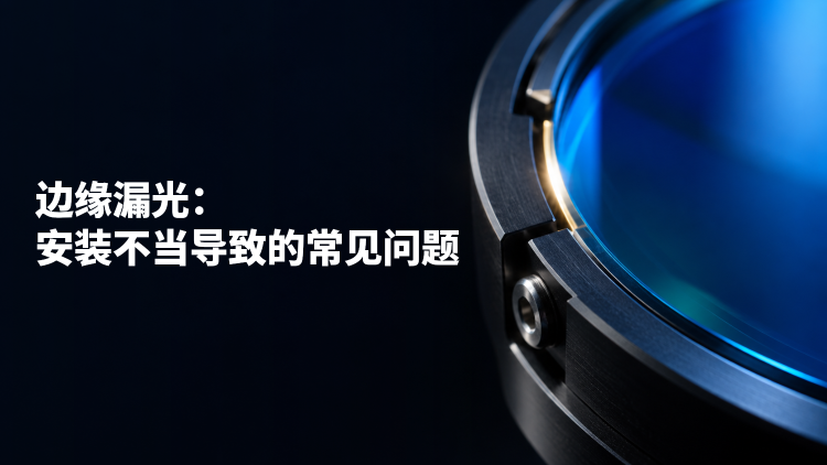
Edge leakage occurs when light reaches the detection channel through a clearance around a filter, an exposed sidewall or a bevel, bypassing the specified coated aperture. A compliant loose optic can shift or tilt. An oversized counterbore, or an incorrect seating depth, can leave an unintended optical entrance even when the retaining ring feels tight.
The result may be a raised background, reduced contrast or a localized bright patch. Reflections along the bypass route can also produce ghosts. Ghosts alone are inconclusive, however: multiple reflections within the intended optical path can produce similar features. A normal spectrum measured through the center of a loose filter therefore does not clear the assembled mount of suspicion.
Consider a filter specified at center wavelength (CWL) 780 nm, full width at half maximum (FWHM) 20 nm, blocking optical density (OD) 6 and angle of incidence (AOI) 0°. These specifications apply within the stated aperture and spectral and angular conditions. They do not characterize the surrounding mechanical clearance.
$$\mathrm{OD}=-\log_{10}T$$
Figure 1 contrasts a blocked peripheral route with an open bypass. At a selected blocking wavelength, let $f$ represent the equivalent fraction of incident power coupled to the detector through the bypass. An incoherent power model gives:
$$T_{\mathrm{sys}}=(1-f)T_{\mathrm{f}}+f,\qquad \mathrm{OD}_{\mathrm{sys}}=-\log_{10}T_{\mathrm{sys}}$$
With $T_{\mathrm{f}}=10^{-6}$ and $f=10^{-4}$, the result is approximately $1.01\times10^{-4}$, or OD4. The coupling fraction includes illumination, scattering and detector acceptance; it is not simply the open-area fraction. Coherent interference is outside this model.
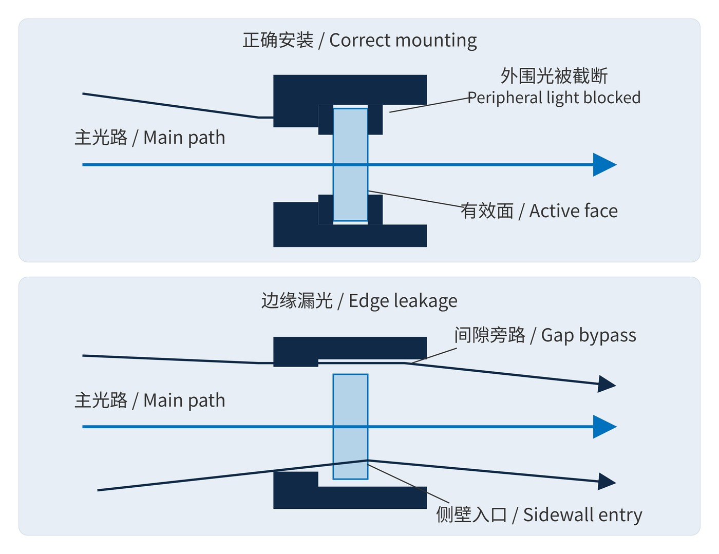
Trace the beam envelope over the full field, maximum cone angle and decenter tolerance before sizing the clear opening. Keep illumination off the bevel and any unspecified coating margin. For a narrow bandpass filter, specify the guaranteed clear aperture separately from the outside diameter.
| Interface | Define | Verify after assembly |
|---|---|---|
| Counterbore and seat | Diameter, thickness, bevel, tolerances and thermal allowance | Stable seating without binding |
| Opaque gasket | Radial overlap and axial shielding depth | No direct opening at worst-case decenter and illumination angle |
| Ring and compliant washer | Contact zone, material and preload range | Even contact; ring does not bottom out first |
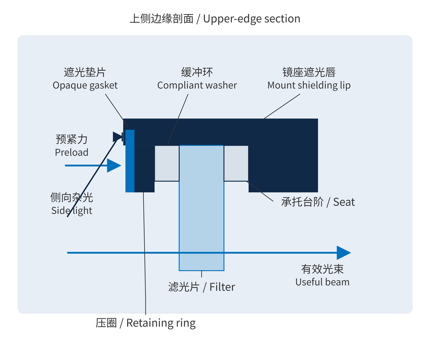
In Figure 2, the retaining ring loads a suitable compliant washer against a supported glass margin. The gasket and a shielding lip obstruct lateral access. A flat gasket that masks the front rim may still leave the sidewall exposed. Calculate overlap after accounting for machining and centering tolerances, while keeping the useful beam unobstructed.
Inspect the assembled stack rather than individual nominal dimensions alone. A ring can reach its mechanical stop before it restrains the glass; an optic can also bind radially even with modest axial preload. Both conditions require a dimensional correction rather than an arbitrary increase in tightening torque.
Black anodizing can reduce reflections from the bore and ring, but visual blackness does not establish low reflectance at the operating wavelength. Test the actual finish and incidence conditions; measured black-material reflectance demonstrates why spectral characterization matters. Blackening cannot close an open geometric path.
Excessive ring torque can distort the optic and introduce stress birefringence, as explained in the technical note on stress in optical glass. There is no universal torque setting: thread friction, glass thickness and washer compliance affect the resulting load. Establish a preload window experimentally and check it across the operating temperature range.
In fluorescence detection, bypass excitation light can overwhelm weak emission. In machine vision, an off-axis lamp may create haze or bright borders. Before specifying deeper blocking, test the mounting path; the useful distinction between OD3, OD4 and OD6 depends on the assembled system.
Tightening is a retention measure, not a substitute for shielding. More torque cannot correct an oversized opening or exposed sidewall. Resolve seating depth, contact geometry and thickness tolerances before increasing preload. Likewise, a background reduction during perimeter masking identifies a peripheral contribution, but does not by itself distinguish a direct gap from sidewall scattering. Use the directional illumination checks to separate those possibilities.
Painting an edge black also does not establish OD6. Any edge treatment needs checks for adhesion, outgassing, cleaning and temperature compatibility, alongside proper mechanical overlap. Record the bare-filter spectrum, assembled background and stress checks with their wavelength and illumination conditions so that the system result can be reproduced.
 365nm Narrow Bandpass Filter | Ø50mm | T>90%
OT-HBP3659050
365nm Narrow Bandpass Filter; FWHM 10nm; transmission >90%; blocking OD5; size Ø50mm; AOI 0°.
 450nm Narrow Bandpass Filter | Ø50mm
OT-HBP4509050
450nm Narrow Bandpass Filter; FWHM 10nm; transmission >90%; blocking OD5; size Ø50mm; AOI 0°.
 525nm Narrow Bandpass Filter | Ø50mm
OT-HBP5259050
525nm Narrow Bandpass Filter; FWHM 10nm; transmission >90%; blocking OD5; size Ø50mm; AOI 0°.
Send us your drawing and spectral targets — an engineer replies with a feasibility check and quotation within one business day.



