Original content by the OOTEE Optics editorial team, drawn from first-hand production line and inspection data. Please credit the source when republishing.
Given limits in expertise and test conditions, the theories, parameters and conclusions here carry no guarantee of absolute accuracy. For technical learning and exchange only - never the sole basis for design, acceptance or selection. Corrections welcome.
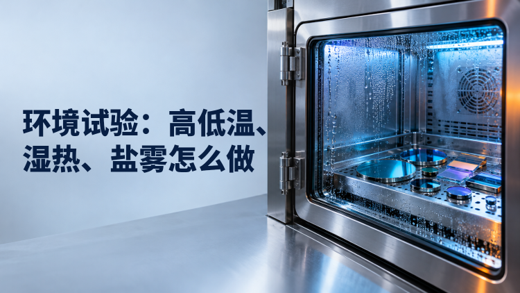
Environmental testing exposes a specimen to defined stresses and compares its optical and physical condition before and afterward. Thermal cycling challenges repeated expansion and contraction; steady humidity probes moisture sensitivity. Cold storage addresses a non-operating state, while salt fog examines susceptibility to a saline atmosphere. Passing one test does not establish resistance to the others.
The practical task is to specify an executable profile and a defensible acceptance decision. ISO 9022-2 addresses cold, heat and humidity for optical instruments; ISO 9022-4 addresses salt mist. Agree severities, recovery and acceptance criteria before testing. All numerical examples below are proposals for discussion, not universal qualification levels.
Expansion mismatch can load coating interfaces. Moisture can alter effective refractive index or penetrate through edges and defects; salt can attack metal films, mounts and seals. Inspect for crazing, delamination, substrate deformation and spectral drift separately.
Fig. 1 starts at 23 °C, cools to −40 °C at 1 °C/min, holds for 60 min, rises to 85 °C for another 60 min, then returns to 23 °C for 120 min of recovery. This ideal chamber program assumes no specimen lag. In practice, start each dwell only after a representative specimen meets the agreed stabilization criterion.
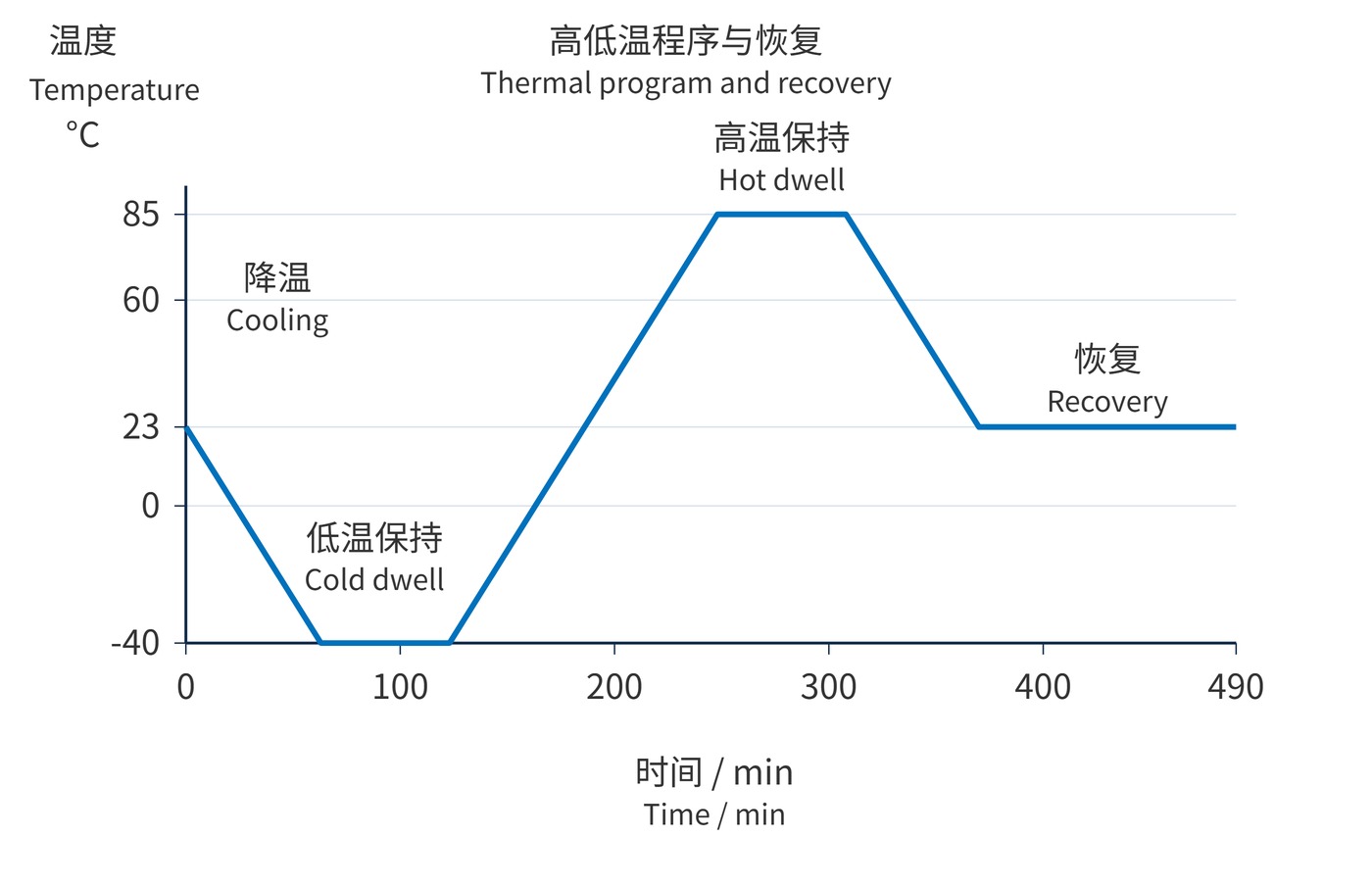
Calculate each linear segment as follows, using signed rate $r$ in °C/min and time in min; a dwell has $r=0$. Define cycle boundaries, repetitions, tolerances, mounting and operating state as well. A controlled ramp is not automatically thermal shock.
$$T(t)=T_i+r(t-t_i)$$
Remeasure center wavelength (CWL), full width at half maximum (FWHM), peak transmission and optical density (OD) over the specified blocking range. Keep angle of incidence (AOI), polarization, beam footprint, measurement locations and reference climate consistent. Residual wavelength shift is:
$$Deltalambda_{mathrm{res}}=lambda_{mathrm{CWL,post}}(T_0,H_0)-lambda_{mathrm{CWL,pre}}(T_0,H_0)$$
Here $T_0$ and $H_0$ are the agreed reference temperature and relative humidity. A hot-state shift is a different measurement; temperature coefficients and humidity stability explain why. Verifying OD6 also requires adequate instrument dynamic range and stray-light control.
Begin with transport, storage and service limits, then check the constraints of the substrate, coating, adhesive and mount. Include bare and assembled specimens where relevant, retain unexposed controls, and agree sample counts and allowable failures. Use separate groups for different stresses unless cumulative damage is the intended question.
| Test | Illustrative exposure | Details still required |
|---|---|---|
| Thermal cycling | −40 to 85 °C; 1 °C/min; 10 cycles | Specimen stabilization, dwells, cycle boundaries |
| Steady humidity | 40 °C; 93% RH; 96 h | Tolerances, condensation prevention, recovery |
| Cold storage | −40 °C; 24 h; non-operating | Packaging, warm-up and unpacking procedure |
| Salt fog | Select solution, temperature and duration by method | pH, fallout, orientation, cleaning and drying |
IEC 60068-2-78:2025 concerns constant-temperature humidity without condensation. Select another appropriate method if condensation is part of service. Keep cold specimens out of moist room air. After salt fog, document deposits and corrosion before the prescribed surface treatment.
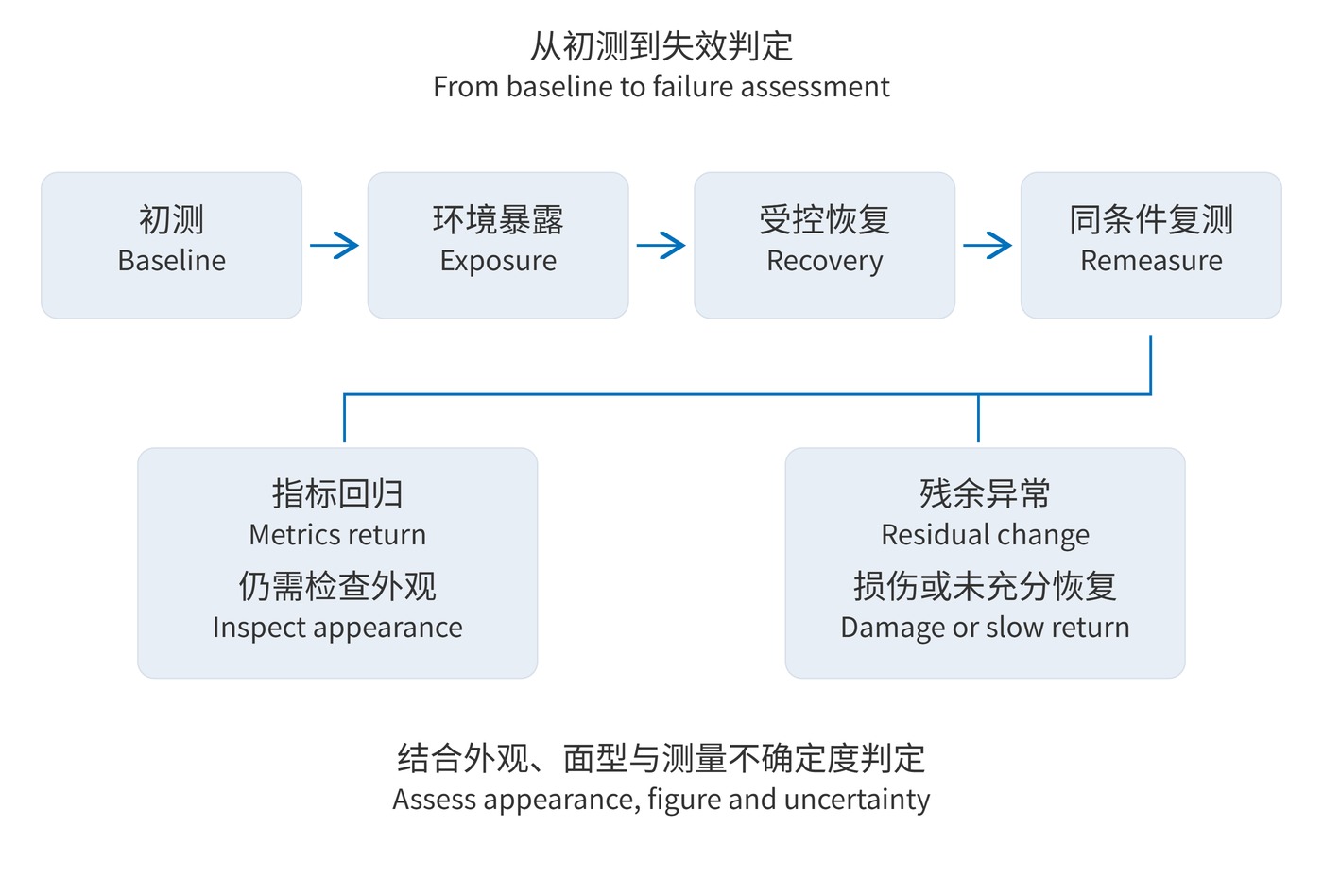
Fig. 2 treats recovery as a controlled stage. One agreed schedule might use 23 ± 2 °C and 50 ± 5% RH for 2 h, with a second reading at 24 h if needed. These are illustrative times; a selected standard takes precedence. Report continuing drift rather than selecting the most favorable reading.
For an outdoor lidar narrow bandpass filter, a discussion specification might be CWL 780 nm, FWHM 20 nm and OD6 over an explicitly defined blocking interval. Example post-recovery limits are ±0.5 nm CWL change and a peak-transmission loss of at most 1 percentage point, with blocking maintained. These are not product guarantees.
Humid imaging assemblies also need scattering or haze checks, surface-figure measurements and assembly inspection. Coastal equipment adds edge corrosion, fasteners and seals. Compare the same microscope locations and support conditions; measure center and edge spectra to avoid hiding localized damage in an average.
A stable return to baseline can support a reversible-response finding under the specified conditions. Persistent shifts, cracks, delamination or permanent figure change indicate irreversible change. Both can coexist: restored CWL does not cancel increased scatter or edge damage.
Apply an agreed uncertainty decision rule. A residual shift of 0.45 nm with expanded uncertainty of 0.10 nm is not an unqualified pass against a ±0.5 nm limit. Salt-fog hours cannot directly predict outdoor lifetime. Retain specimen identities, exposure logs, recovery timestamps, raw measurements and defect photographs for traceable decisions.
 365nm Narrow Bandpass Filter | Ø50mm | T>90%
OT-HBP3659050
365nm Narrow Bandpass Filter; FWHM 10nm; transmission >90%; blocking OD5; size Ø50mm; AOI 0°.
 450nm Narrow Bandpass Filter | Ø50mm
OT-HBP4509050
450nm Narrow Bandpass Filter; FWHM 10nm; transmission >90%; blocking OD5; size Ø50mm; AOI 0°.
 525nm Narrow Bandpass Filter | Ø50mm
OT-HBP5259050
525nm Narrow Bandpass Filter; FWHM 10nm; transmission >90%; blocking OD5; size Ø50mm; AOI 0°.
Send us your drawing and spectral targets — an engineer replies with a feasibility check and quotation within one business day.



