Original content by the OOTEE Optics editorial team, drawn from first-hand production line and inspection data. Please credit the source when republishing.
Given limits in expertise and test conditions, the theories, parameters and conclusions here carry no guarantee of absolute accuracy. For technical learning and exchange only - never the sole basis for design, acceptance or selection. Corrections welcome.
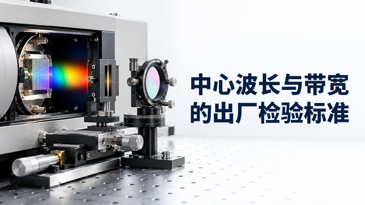
Factory inspection of center wavelength (CWL) and full width at half maximum (FWHM) has two decisions: whether an inspected filter meets its limits, and whether a lot qualifies for release. FWHM is the full distance between half-height crossings. A peak wavelength, a midpoint and a spectral centroid need not coincide.
Consider illustrative requirements of CWL 780 nm ±1 nm and FWHM 20 nm ±2 nm. Both must pass. A separate optical density (OD) requirement, such as OD6 over a specified blocking interval, requires its own test. These example limits are not universal factory standards.
For a single passband, agree on baseline treatment, locate half the peak transmission and interpolate between adjacent samples at each crossing. Here CWL means the midpoint of those crossings. Ripple or multiple peaks requires an agreed search window and crossing rule before testing.
$$T(\lambda_1)=T(\lambda_2)=\frac{T_{\mathrm{peak}}}{2},\qquad \mathrm{CWL}=\frac{\lambda_1+\lambda_2}{2},\qquad \mathrm{FWHM}=\lambda_2-\lambda_1$$
Specify angle of incidence (AOI), beam cone, polarization, temperature and spot diameter. Acceptance at 0° does not establish acceptance at an operating AOI of 10°; angular shift changes the spectrum. For tilted filters, define whether s, p or an unpolarized average is tested.
For the 20 nm example, a starting setup might use 23 °C ±2 °C, AOI 0°, a 750–810 nm scan, 0.1 nm sampling and 0.2 nm instrument spectral bandwidth. Sampling interval is not resolution. Repeat with narrower instrument bandwidth to establish that remaining edge and width changes fit the measurement budget. Check wavelength calibration, remounting repeatability and stray light as well.
Specification limits $L,H$ and acceptance limits are different concepts. Simple acceptance uses the specification limits directly; a guard band narrows the accepted interval. Select the rule before seeing results. One possible agreement uses expanded uncertainty $U$ as the guard band $g$:
$$L+g\leq x\leq H-g,\qquad g=U$$
This is an example decision rule, not a universal requirement or a promise of zero decision risk. State the uncertainty conditions and factor $k$ used to calculate expanded uncertainty. ILAC G8 discusses guard bands and conformity decisions.
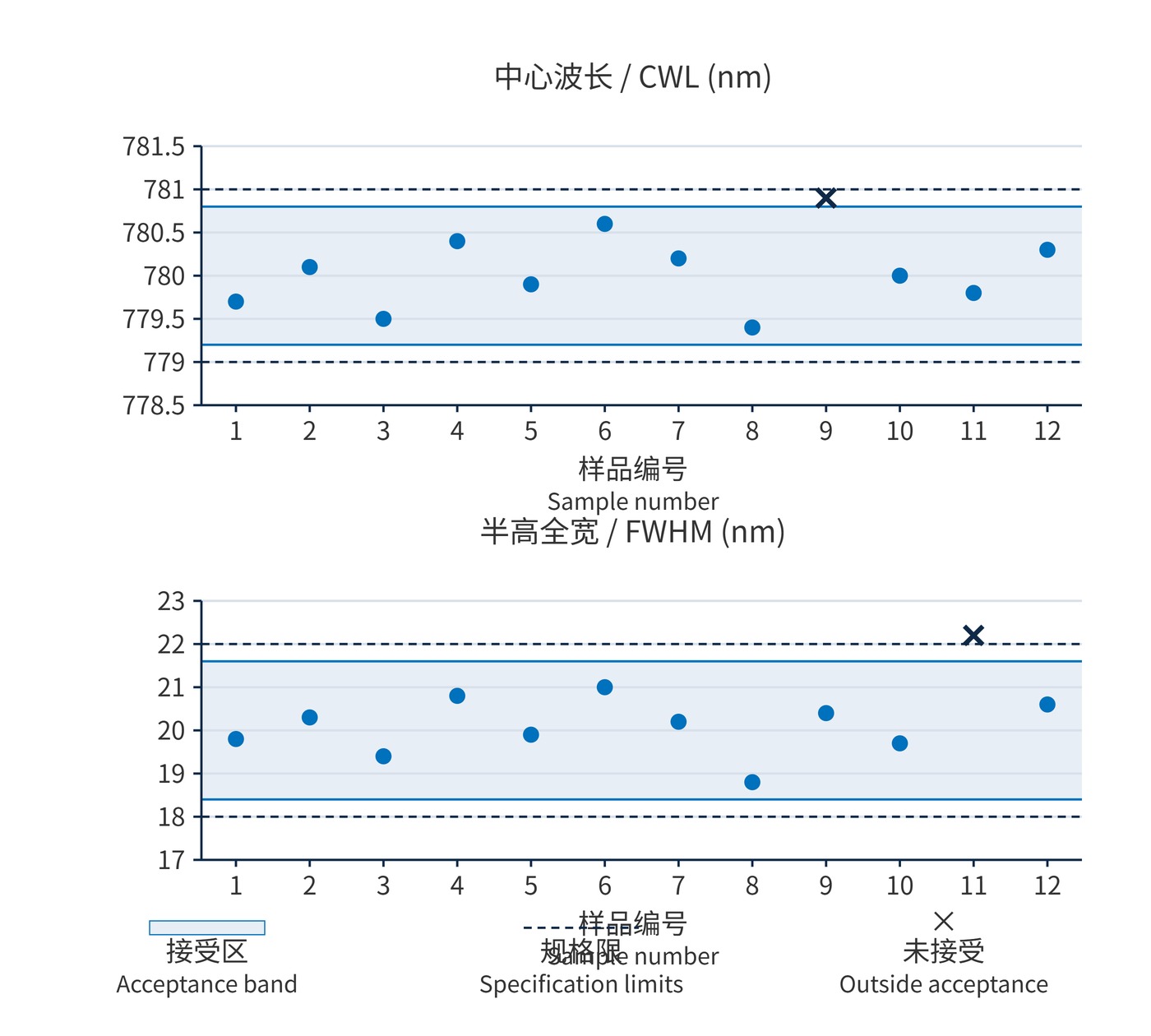
In Fig. 1, $U=0.2\,\mathrm{nm}$ gives a CWL acceptance interval of 779.2–780.8 nm. For width, $U=0.4\,\mathrm{nm}$ gives 18.4–21.6 nm. Separate panels avoid mixing scales. Sample 9 measures 780.9 nm: within specification, but outside acceptance. Sample 11 has a 22.2 nm width, beyond specification. Define the disposition of results outside acceptance, including any retest procedure; repeated testing until a pass is not a decision rule.
The inspection level helps relate lot size to sample size. The acceptance quality limit (AQL) indexes a scheme for continuing lots; it is neither a guaranteed maximum defect percentage in each lot nor a quality guarantee. Choose the standard and edition, inspection severity, level and AQL, then obtain sample size and acceptance/rejection numbers Ac/Re. “AQL 1.0” alone is insufficient. NIST’s sampling guidance describes the associated producer and consumer risks.
Draw randomly across the lot. When counting nonconforming units, a filter failing either required characteristic counts once, even if both fail; apply Ac/Re to that count. Critical applications may require every filter to be tested. The 12 filters in Fig. 1 illustrate decisions and do not represent a standard sampling plan.
For a narrow bandpass filter in laser detection, a center measurement may miss an unacceptable peripheral region. Fig. 2 shows a center-plus-four-point arrangement. If every location must comply, a spatial average cannot rescue a failing location.
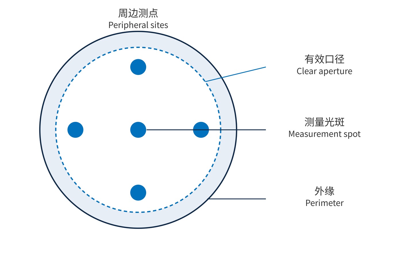
A 25 mm filter could have a 21 mm clear aperture, 2 mm spots and peripheral spot centers 8 mm from its center. Each spot then lies fully inside the aperture. Include agreed peripheral positions inside the clear aperture; exclude bevels and explicitly nonworking margins. If illumination reaches those margins, revise the aperture and measurement map. Five locations on one filter still constitute one sampled unit.
The distinction matters when comparing suppliers or repeating incoming inspection. A larger spot averages a different area, while a different mounting angle changes the optical condition. Align these settings before attributing a disagreement to the coating. A predefined site map also prevents selective omission of an inconvenient peripheral result.
A reproducible acceptance decision requires a shared spectral definition, measurement setup, spatial scope and sampling rule.
 365nm Narrow Bandpass Filter | Ø50mm | T>90%
OT-HBP3659050
365nm Narrow Bandpass Filter; FWHM 10nm; transmission >90%; blocking OD5; size Ø50mm; AOI 0°.
 450nm Narrow Bandpass Filter | Ø50mm
OT-HBP4509050
450nm Narrow Bandpass Filter; FWHM 10nm; transmission >90%; blocking OD5; size Ø50mm; AOI 0°.
 525nm Narrow Bandpass Filter | Ø50mm
OT-HBP5259050
525nm Narrow Bandpass Filter; FWHM 10nm; transmission >90%; blocking OD5; size Ø50mm; AOI 0°.
Send us your drawing and spectral targets — an engineer replies with a feasibility check and quotation within one business day.



