Original content by the OOTEE Optics editorial team, drawn from first-hand production line and inspection data. Please credit the source when republishing.
Given limits in expertise and test conditions, the theories, parameters and conclusions here carry no guarantee of absolute accuracy. For technical learning and exchange only - never the sole basis for design, acceptance or selection. Corrections welcome.

The entrance surface is the first surface reached by the incident beam; the exit surface is where transmitted light leaves. Edge dots, lines, notches and arrows can identify a specified optical orientation. Serial numbers, lot codes and micro-engraved characters serve a different purpose: traceability. A dot is not automatically an authentication feature, and a serial number does not identify the entrance surface.
There is no universal arrow convention. An arrow may point toward the preferred entrance face or along beam propagation. A dot may lie on a face margin or on the edge. Match the actual mark to a controlled drawing that defines the viewing direction and surface names. Reflected color is unreliable, especially when both faces are coated.
Inspect the mark before clamping the optic: a mount can hide the only useful reference. Record the visible edge and its relationship to the source so a later replacement can reproduce the approved orientation without relying on memory.
For a dichroic used in reflection, facing the primary coating toward the source usually avoids sending the desired reflected beam through the substrate first. This reduces opportunities for substrate absorption, fluorescence and ghost reflections. Fig. 1 compares the paths: with the primary coating at the rear, the main reflected beam makes a round trip through the substrate, while the entrance interface generates a separate reflection.
For substrate absorption alone, let $\alpha$ be the absorption coefficient, $d$ the thickness and $\theta_t$ the internal refraction angle. The one-way path length is $L$:
$$L=\frac{d}{\cos\theta_t},\qquad \frac{I_{\mathrm{return}}}{I_{\mathrm{enter}}}=\exp(-2\alpha L)$$
With $d=1\,\mathrm{mm}$, $\theta_t=28^{\circ}$ and $\alpha=0.01\,\mathrm{mm}^{-1}$, the round-trip absorption factor is approximately 0.978. Interface transmission and coating reflectance are excluded, so this is not the component reflectance. A parallel plate produces parallel, displaced reflections; wedge and alignment errors can also introduce angular separation.
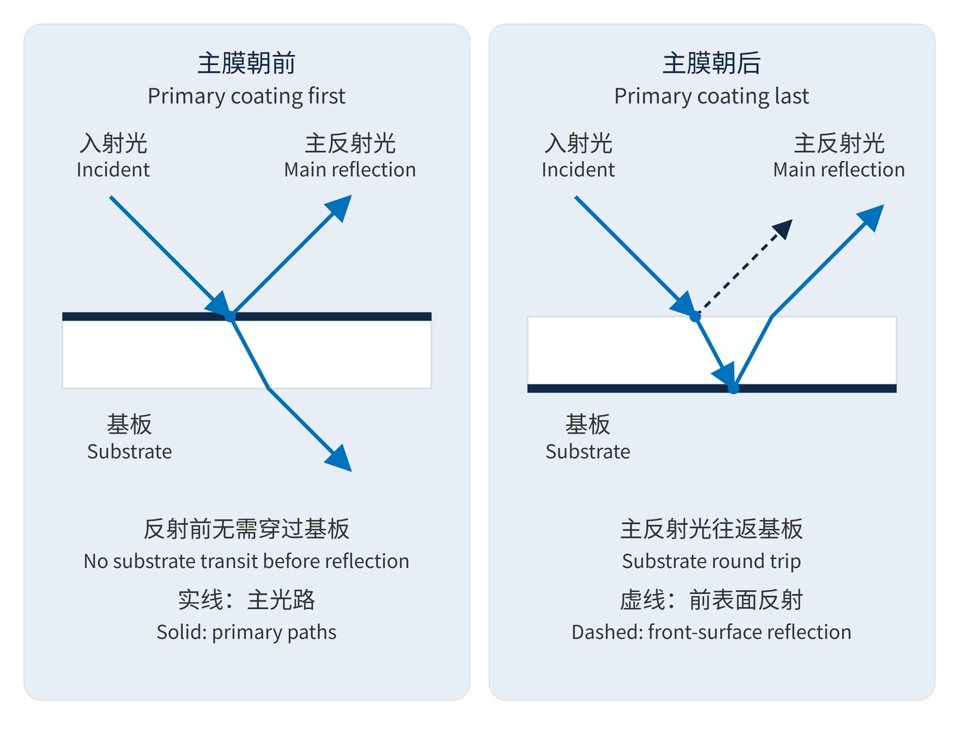
Transmission requires a separate argument. For a linear reciprocal optic with identical external media, corresponding reciprocal modes have equal power transmittance. Reversal therefore does not necessarily shift the passband or weaken blocking. It can change reflection, absorption distribution and fluorescence excitation, with consequences for the background collected by the instrument. Optical density (OD) is defined at a specified wavelength by:
$$\mathrm{OD}(\lambda)=-\log_{10}T(\lambda),\qquad T=\frac{P_{\mathrm{out}}}{P_{\mathrm{in}}}$$
If direct leakage is $10^{-6}$ and reflected stray light contributes another $10^{-5}$ relative to incident power at the detector, their sum is $1.1\times10^{-5}$, equivalent to OD4.96. This describes system rejection, not a new measured OD for the filter itself.
A transmission filter specified by center wavelength (CWL) 780 nm, full width at half maximum (FWHM) 20 nm and OD6 blocking also needs a blocking interval, angle of incidence (AOI), polarization, clear aperture and preferred entrance face. For dichroic mirrors, specify the reflected port and working AOI, for example 45°. Transmission requirements alone do not define the installation.
| Check | Required drawing or inspection information |
|---|---|
| Direction | Surface S1/S2 definitions, arrow meaning and viewing direction |
| Mark location | Position outside the clear aperture, dimensions and mount visibility |
| Identity | Serial or lot code linked to the inspection report |
| Durability | Permitted solvents, wiping procedure and legibility acceptance method |
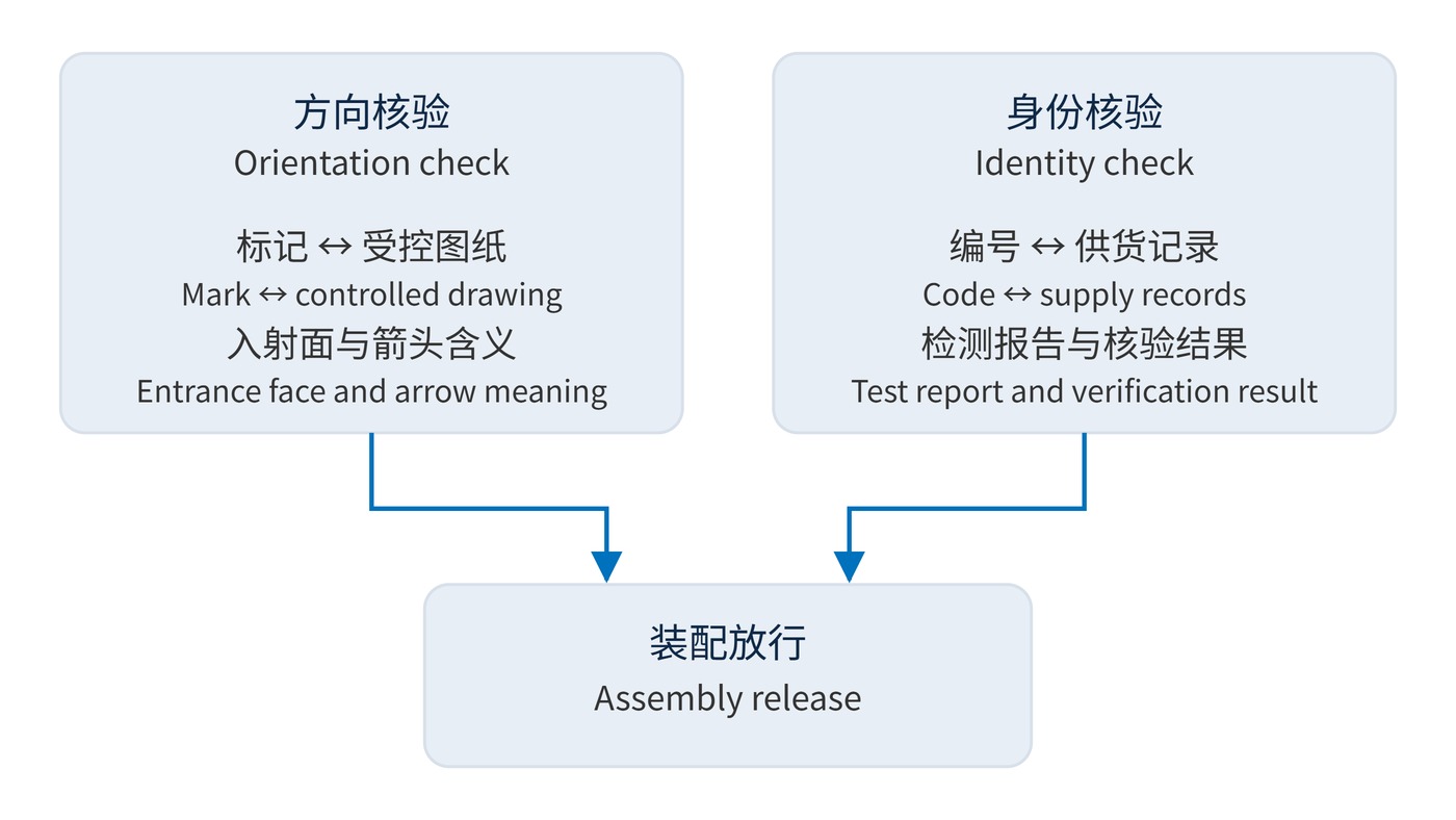
Keep orientation approval separate from identity verification, as shown in Fig. 2. Ordinary engraving, QR codes and package labels can be copied. Authentication needs a match to controlled supply records, an authorized verification result and, where necessary, spectral inspection. Microtext or a distinctive texture is useful only when reference evidence and acceptance rules have been agreed.
In fluorescence instruments, excitation light entering a fluorescent substrate first can increase the emission-channel background even when forward and reverse transmission spectra look similar. In a stack, reversal changes reflecting-surface positions and stray-light return paths. Mark each entrance face, rejected-beam path and stop on the assembly drawing so rejected light does not return through adjacent optics to the detector.
For machine-vision replacements and instrument servicing, retain photographs of edge marks, mount references and the associated test report. Compare background and useful signal after reassembly with AOI, polarization and detector acceptance held constant. A transmission retest should also control baseline and dynamic range, as described in spectrometer transmission measurement.
 365nm Narrow Bandpass Filter | Ø50mm | T>90%
OT-HBP3659050
365nm Narrow Bandpass Filter; FWHM 10nm; transmission >90%; blocking OD5; size Ø50mm; AOI 0°.
 450nm Narrow Bandpass Filter | Ø50mm
OT-HBP4509050
450nm Narrow Bandpass Filter; FWHM 10nm; transmission >90%; blocking OD5; size Ø50mm; AOI 0°.
 525nm Narrow Bandpass Filter | Ø50mm
OT-HBP5259050
525nm Narrow Bandpass Filter; FWHM 10nm; transmission >90%; blocking OD5; size Ø50mm; AOI 0°.
Send us your drawing and spectral targets — an engineer replies with a feasibility check and quotation within one business day.



