Original content by the OOTEE Optics editorial team, drawn from first-hand production line and inspection data. Please credit the source when republishing.
Given limits in expertise and test conditions, the theories, parameters and conclusions here carry no guarantee of absolute accuracy. For technical learning and exchange only - never the sole basis for design, acceptance or selection. Corrections welcome.

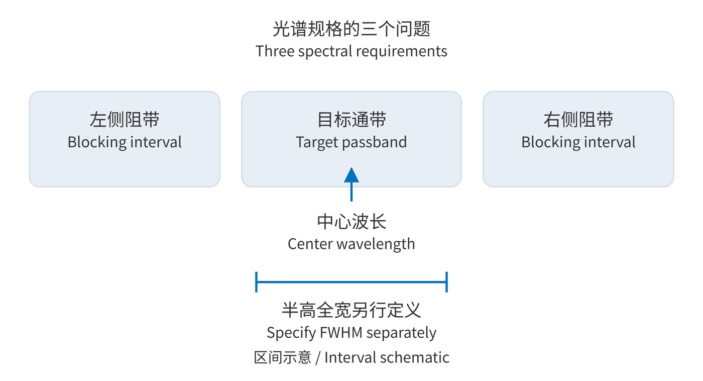
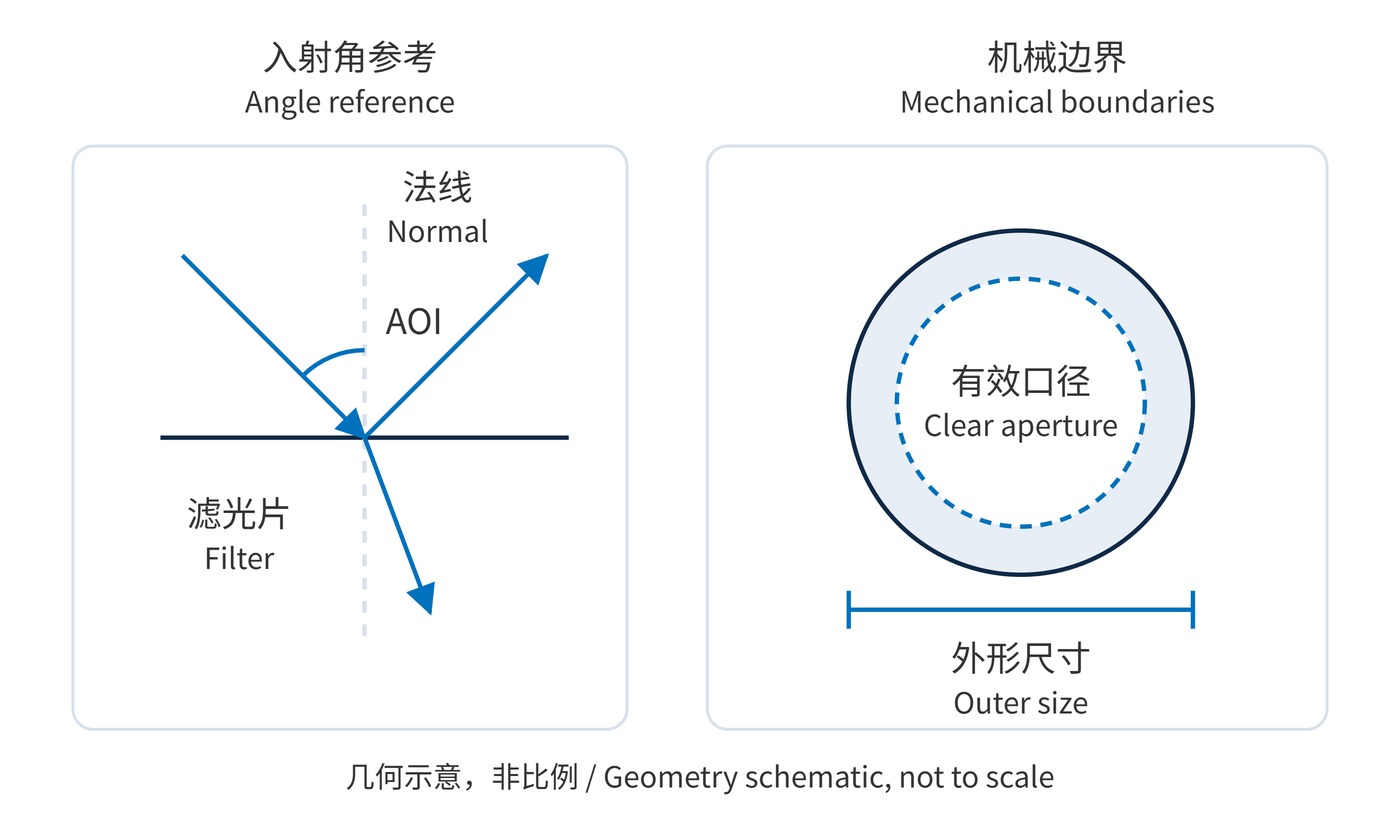
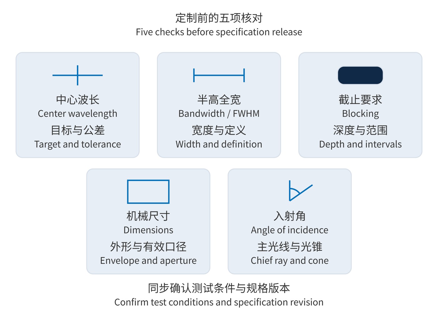
A useful custom filter request starts with five groups: center wavelength (CWL), full width at half maximum (FWHM), out-of-band blocking, mechanical dimensions, and angle of incidence (AOI). Together they locate the passband, set its width, constrain unwanted light, define the part that fits the mount, and describe how light reaches it.
These are specification groups rather than five isolated numbers. Each needs a target, a tolerance, and operating conditions. “780 nm filter” is not enough for a design review, while an unlabelled reference trace cannot establish acceptance criteria.
Interference filters select wavelengths through optical layer thicknesses. Their response also depends on illumination angle, polarization, and temperature. Fig. 1 separates the spectral requirements without implying a measured response.
$$T(\lambda_1)=T(\lambda_2)=\frac{T_{\mathrm{peak}}}{2},\qquad \mathrm{FWHM}=\lambda_2-\lambda_1$$
$$\mathrm{OD}(\lambda)=-\log_{10}T(\lambda)$$
Here $T$ is a fractional transmittance between 0 and 1. OD6 means $10^{-6}$, or 0.0001% transmission. System background may remain much higher because of stray light or leakage around the part.
Start with the source spectrum and drift, detector sensitivity, and interference wavelengths. Use CWL and FWHM to shortlist narrow bandpass filters, then check the complete blocking intervals and illumination geometry.
The following values illustrate a discussion specification, not a stock product or a performance commitment. A peak transmission requirement does not set the transmission floor at the passband edges.
| Group | Example requirement | Acceptance detail |
|---|---|---|
| CWL | 780±1 nm | Midpoint of the half-peak crossings |
| Bandwidth | 20±2 nm | FWHM from the same trace |
| Blocking | OD≥6 at 400–740 nm and 820–1100 nm | Minimum OD throughout both intervals |
| Mechanical | Diameter 25.0 mm; thickness 2.0±0.1 mm | Diameter +0/−0.1 mm; clear aperture≥22.0 mm |
| Angle | AOI 0°; cone half-angle≤2° | Unpolarized light; record the test angular distribution |
Supplementary requirements might include peak transmission≥90% at 23±2 °C. Agree on scan increment, instrument spectral bandwidth, and sampling positions within the clear aperture. An OD6 measurement needs adequate dynamic range and stray-light control; a result below the instrument floor is not automatically proof of compliance.
Mark firm limits separately from negotiable targets. A fixed mounting bore may impose an absolute diameter limit, whereas an unsettled source choice may leave several acceptable center wavelengths. Explain the system reason for tight tolerances before carrying them into manufacturing and inspection. When one requirement changes, review the other four: a revised beam angle, for instance, can affect both spectral alignment and the footprint required within the clear aperture. Procurement should retain the approved revision rather than assemble requirements from several email versions.
A laser receiver starts with laser wavelength and drift, then checks rays at the edge of its field of view. Narrowing the passband can reject useful light if angular effects are omitted. Include the effect of incidence angle in the optical budget.
Fluorescence detection often gives blocking against intense excitation light the highest priority, with detector sensitivity setting the required blocking range. Machine vision may instead be constrained by lens mounting space and a converging beam. Naming an application provides context; it cannot replace measurable limits.
Watch for OD without a range, outer diameter without clear aperture, mount tilt used in place of optical AOI, and average transmission confused with peak transmission. Add temperature, polarization, laser irradiance, or environmental requirements whenever they affect performance.
Use the checklist in Fig. 3 to confirm values, tolerances, and conditions before releasing the request. Freeze the specification revision together with the mechanical drawing and test method, so the design, sample report, and production acceptance all use the same definitions.
 365nm Narrow Bandpass Filter | Ø50mm | T>90%
OT-HBP3659050
365nm Narrow Bandpass Filter; FWHM 10nm; transmission >90%; blocking OD5; size Ø50mm; AOI 0°.
 450nm Narrow Bandpass Filter | Ø50mm
OT-HBP4509050
450nm Narrow Bandpass Filter; FWHM 10nm; transmission >90%; blocking OD5; size Ø50mm; AOI 0°.
 525nm Narrow Bandpass Filter | Ø50mm
OT-HBP5259050
525nm Narrow Bandpass Filter; FWHM 10nm; transmission >90%; blocking OD5; size Ø50mm; AOI 0°.
Send us your drawing and spectral targets — an engineer replies with a feasibility check and quotation within one business day.



