Original content by the OOTEE Optics editorial team, drawn from first-hand production line and inspection data. Please credit the source when republishing.
Given limits in expertise and test conditions, the theories, parameters and conclusions here carry no guarantee of absolute accuracy. For technical learning and exchange only - never the sole basis for design, acceptance or selection. Corrections welcome.

Grinding and polishing achieve flatness through controlled material removal and repeated measurement. A bright surface is insufficient evidence: a polished optic can still have curvature, local high spots or a rolled edge. Flatness describes departure from a plane across a specified aperture; roughness describes much finer texture.
Grinding establishes geometry and thickness. Successively finer abrasives reduce damage left by earlier stages. Polishing removes remaining damage, improves texture and corrects figure. These tasks need a planned removal allowance. The specification conventions are discussed in the guide to surface flatness acceptance; the focus here is how manufacturing converges on that specification.
Preston’s empirical relationship links local removal depth $h$ to pressure $p$, relative speed $v$ and polishing time $t$. The coefficient $k$ reflects the material, slurry, pad and process condition; it must be established for the actual process.
$$h(x,y)=k\int_0^t p(x,y,\tau)v(x,y,\tau)\,\mathrm{d}\tau$$
In SI units, depth is in $\mathrm{m}$, pressure in $\mathrm{Pa}$, speed in $\mathrm{m/s}$ and time in $\mathrm{s}$. Increasing pressure may increase removal, but can also bend a thin blank and change tool contact. A constant-coefficient model has practical limits.
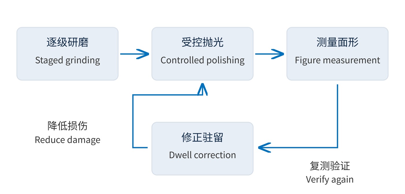
Fig. 1 shows the manufacturing loop: measure the figure, adjust the removal process, and measure again. Corrective polishing changes dwell time, tool motion or contact conditions to remove more material from high regions. Tool footprint and its removal function limit which spatial features can be corrected.
Subsurface damage (SSD) also matters. Grinding cracks may remain beneath a visibly polished surface. Clean the part, tools and fluid system between abrasive grades, and establish removal allowances using a qualified process. Work published in Applied Optics links texture and damage depth under defined conditions; it does not provide a universal conversion for every material and process.
Start with material, dimensions, thickness and clear aperture. As an illustrative requirement, a 25 mm diameter, 3 mm thick glass blank might need single-surface peak-to-valley (PV) error no greater than $\lambda/10$ over a 22 mm aperture at a reference wavelength of 632.8 nm. This corresponds to 63.28 nm of surface height and is not a product guarantee.
For residual height $z$ after removing piston and tilt, calculate PV over the agreed aperture $A$. State any additional terms removed. Subtracting curvature from a nominally flat optic can hide a significant figure error.
$$\mathrm{PV}=\max_{(x,y)\in A}z(x,y)-\min_{(x,y)\in A}z(x,y)$$
| Item | Conditions to record |
|---|---|
| Figure data | Aperture, PV, root mean square (RMS), reference wavelength and removed terms |
| Test setup | Support points, clamping force, thermal stability and orientation |
| Acceptance stage | Uncoated substrate, coated optic or installed assembly |
In normal-incidence interferometry with one reflection from the test surface, reflected optical path error is approximately twice the surface height error. Identify what the software reports before applying any conversion. RMS adds information about the overall distribution, while local defects and edges still require inspection.
For repeat orders, ask for the same reporting convention and support arrangement each time. A changed aperture or a different curvature-removal setting can make two apparently similar numbers incomparable. Preserve the measured map as well as the summary values, so any persistent edge or local feature can be traced back to the process.
A beam splitter in a collimated beam can transfer substrate curvature into reflected wavefront error. Transmission depends on both surfaces, thickness variation and material homogeneity. A single-surface flatness result cannot predict every transmitted-wavefront effect.
Large apertures require repeatable support so gravitational sag is not mistaken for a manufacturing high spot. Thin blanks are particularly sensitive to clamping: an optic polished flat under load may spring back after release.
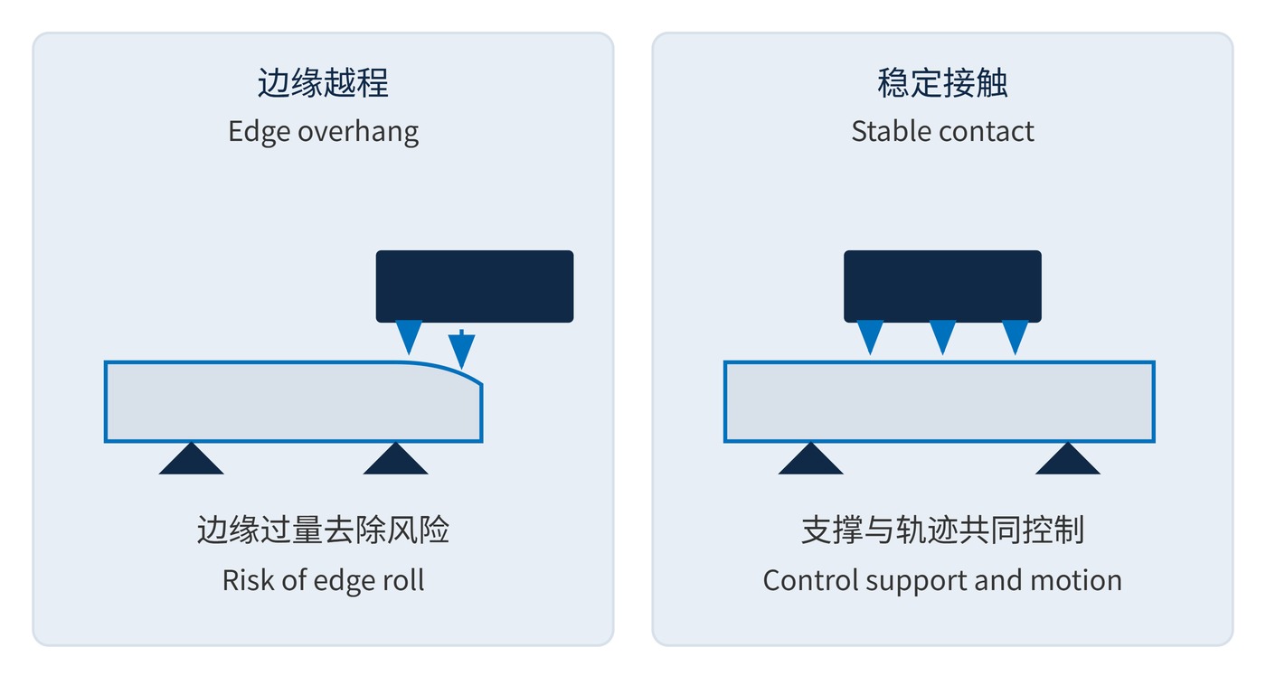
As Fig. 2 indicates, tool overhang changes contact near the edge and can cause excess removal. Tool conditioning, trajectory and overhang control help manage this effect. Verify the result after releasing the fixture and returning the part to the agreed test condition.
Keep before-and-after measurements with consistent aperture and processing rules. Traceable records connect damage removal, figure correction and verification of the delivered condition.
 365nm Narrow Bandpass Filter | Ø50mm | T>90%
OT-HBP3659050
365nm Narrow Bandpass Filter; FWHM 10nm; transmission >90%; blocking OD5; size Ø50mm; AOI 0°.
 450nm Narrow Bandpass Filter | Ø50mm
OT-HBP4509050
450nm Narrow Bandpass Filter; FWHM 10nm; transmission >90%; blocking OD5; size Ø50mm; AOI 0°.
 525nm Narrow Bandpass Filter | Ø50mm
OT-HBP5259050
525nm Narrow Bandpass Filter; FWHM 10nm; transmission >90%; blocking OD5; size Ø50mm; AOI 0°.
Send us your drawing and spectral targets — an engineer replies with a feasibility check and quotation within one business day.