Original content by the OOTEE Optics editorial team, drawn from first-hand production line and inspection data. Please credit the source when republishing.
Given limits in expertise and test conditions, the theories, parameters and conclusions here carry no guarantee of absolute accuracy. For technical learning and exchange only - never the sole basis for design, acceptance or selection. Corrections welcome.
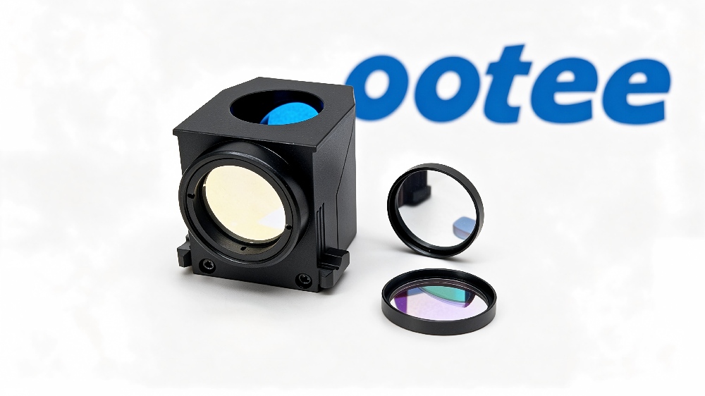
When running multiplex fluorescence PCR, the hardest part is rarely primer design — it is channel crosstalk: a signal meant for FAM also shows up in HEX. In most cases the root cause is a mismatched filter set. Here is the four-step method we use when supporting customers.
Write down each dye with its excitation and emission peaks. Common panels:
| Dye | Excitation | Emission | Emission bandwidth |
|---|---|---|---|
| FAM / SYBR | 494 nm | 520 nm | 20–30 nm |
| HEX / VIC | 535 nm | 556 nm | 20–30 nm |
| ROX / Texas Red | 587 nm | 610 nm | 20–30 nm |
| Cy5 | 650 nm | 670 nm | 25–40 nm |
When adjacent emission peaks are less than 30 nm apart (FAM 520 vs. HEX 556), bandwidths must be narrowed or the channels will bleed into each other.
Each channel relies on three components working together:
The dichroic is often underestimated, yet it governs both excitation reflection efficiency and emission transmission. Our dichroic mirror series offers standard edges and full customization.
Dimensional tolerance (±0.1 mm is typical), substrate (K9 / fused silica / borosilicate), incidence angle (0° or 45°), whether an AR coating is needed, and the operating temperature and humidity range. None of these change optical performance, but all of them decide whether the part fits and survives.
A customer's four-channel qPCR instrument showed roughly 8% crosstalk in the Cy5 channel. Investigation: the ROX emission filter had been widened to 40 nm, and its tail overlapped Cy5's 670 nm region. Narrowing the bandwidth to 30 nm and raising long-wavelength blocking from OD4 to OD6 brought crosstalk below 0.5%.
OOTEE Optics supplies PCR fluorescence filter sets matched to common dye panels, and can redesign a complete set from scratch. Send us your dye list and optical layout and we will propose the full three-element configuration.
 365nm Narrow Bandpass Filter | Ø50mm | T>90%
OT-HBP3659050
365nm Narrow Bandpass Filter; FWHM 10nm; transmission >90%; blocking OD5; size Ø50mm; AOI 0°.
 450nm Narrow Bandpass Filter | Ø50mm
OT-HBP4509050
450nm Narrow Bandpass Filter; FWHM 10nm; transmission >90%; blocking OD5; size Ø50mm; AOI 0°.
 525nm Narrow Bandpass Filter | Ø50mm
OT-HBP5259050
525nm Narrow Bandpass Filter; FWHM 10nm; transmission >90%; blocking OD5; size Ø50mm; AOI 0°.
Send us your drawing and spectral targets — an engineer replies with a feasibility check and quotation within one business day.



