Original content by the OOTEE Optics editorial team, drawn from first-hand production line and inspection data. Please credit the source when republishing.
Given limits in expertise and test conditions, the theories, parameters and conclusions here carry no guarantee of absolute accuracy. For technical learning and exchange only - never the sole basis for design, acceptance or selection. Corrections welcome.
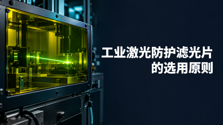
A laser safety protective filter attenuates specified laser wavelengths in a viewing window, receiver path or personal protective assembly. Selection has two separate objectives: reduce accessible radiation to an acceptable level, and keep the barrier intact under the expected exposure. Tint alone establishes neither.
Start by identifying what needs protection. A detector input limit is an equipment specification. The maximum permissible exposure (MPE) for a person depends on wavelength, exposure duration and pulse conditions. These limits are not interchangeable. All numerical examples below use hypothetical engineering assumptions.
Optical density (OD) expresses wavelength-dependent attenuation, with transmittance $T$ written as a fraction. OD6 means one part per million transmission; it does not specify the incident power that a filter can withstand.
$$\mathrm{OD}(\lambda)=-\log_{10}T(\lambda),\qquad E_{\mathrm{out}}=E_{\mathrm{in}}10^{-\mathrm{OD}(\lambda)}$$
Absorbing filters turn intercepted energy into heat. Reflecting filters redirect it and need a controlled termination. Angle of incidence (AOI), polarization, temperature and position across the aperture can change attenuation. Specify a minimum OD throughout every hazardous wavelength interval, rather than a value at one wavelength.
Fig. 1 shows that each tenfold increase in incident irradiance requires one additional OD when the output limit is fixed. The separate endurance boundary is an assumed component constraint. Increasing OD cannot establish reliability beyond that boundary.
$$\mathrm{OD}_{\mathrm{req}}=\max\!\left(0,\log_{10}\frac{E_{\mathrm{in}}}{E_{\mathrm{allow}}}\right)$$
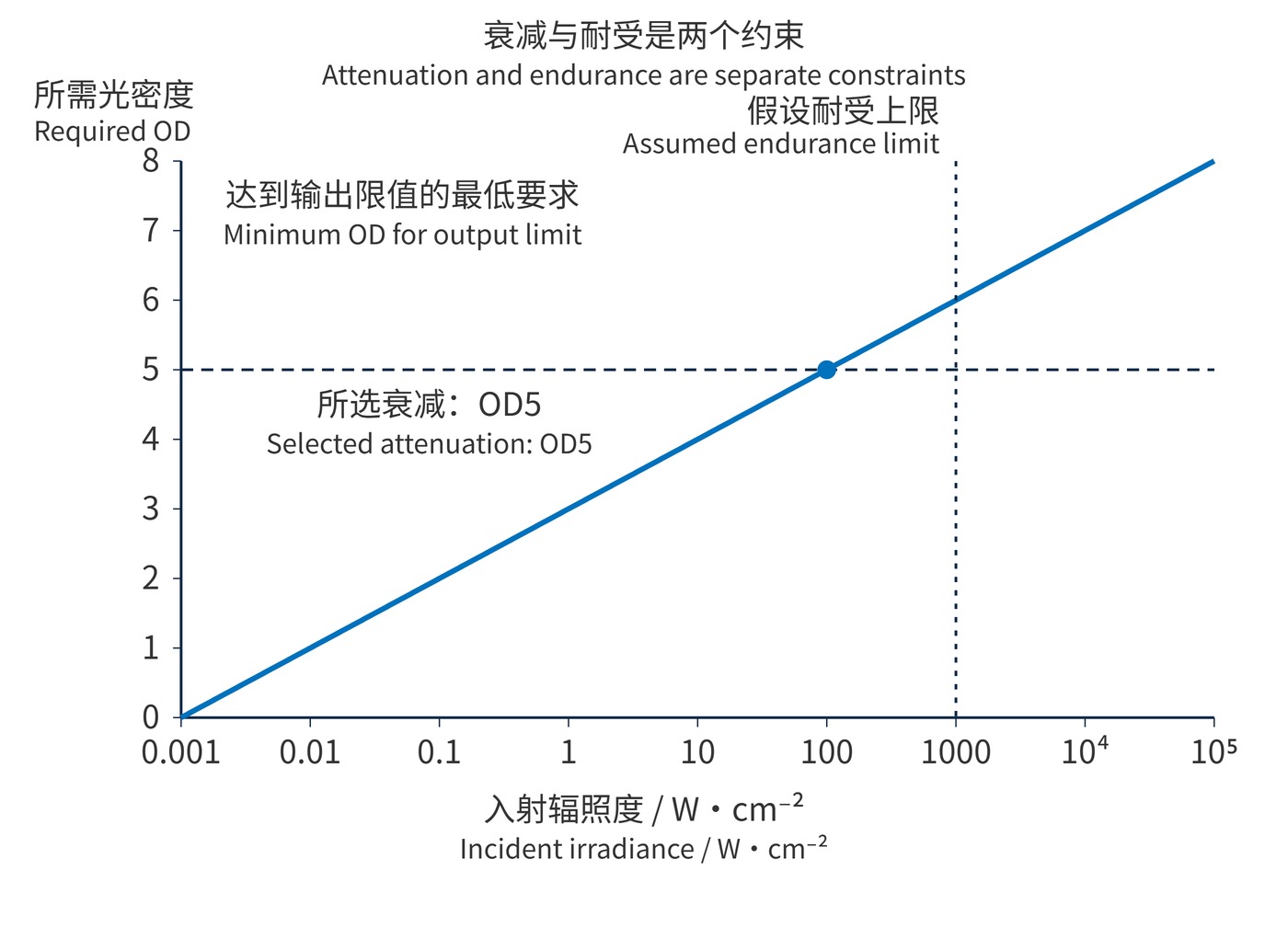
Fig. 1 conditions: pointwise calculation for continuous light at a fixed wavelength; assumed output limit 0.001 W/cm² and endurance boundary 1000 W/cm². Neither is an eye exposure limit.
OSHA’s hazard assessment guidance explains that exposure and MPE must use matching units and the prescribed limiting aperture. Pulsed sources require checks for individual pulses, average exposure and repetitive-pulse effects. Substituting peak power into a continuous-wave calculation is insufficient.
Example 1: a uniform 1064 nm continuous beam delivers 1 W across 0.01 cm², giving 100 W/cm². For an assumed equipment output limit of 0.001 W/cm², OD5 reaches the limit exactly. OD6 adds a tenfold attenuation margin. This is not an eyewear recommendation; a Gaussian beam also requires evaluation of its local peak.
Example 2: a 1064 nm, 10 ns pulse delivers 0.2 J across a uniform 0.02 cm² spot. Its fluence is 10 J/cm². Even if the assumed output requirement needs only OD4, a damage threshold of 2 J/cm² under matching test conditions is exceeded by a factor of 5. The filter is unsuitable. Repeated exposure also requires cumulative-damage assessment.
$$H_{\mathrm{in}}=\frac{Q}{A}=\frac{0.2\,\mathrm{J}}{0.02\,\mathrm{cm}^{2}}=10\,\mathrm{J/cm}^{2}$$
A laser-induced damage threshold is comparable only with its wavelength, pulse duration, spot definition and test method. A typical value measured at one location is not an assembly endurance declaration for an observation window exposed during a fault.
| Framework | Information to read | Invalid inference |
|---|---|---|
| EN 207 eyewear marking | Wavelength interval, D/I/R/M operating mode, LB scale number and applicable conformity markings | An LB number is not an OD specification for arbitrary operating conditions |
| ANSI Z136 use framework | Wavelength interval and required OD established through hazard evaluation | A generic ANSI claim cannot replace spectral and endurance evidence |
In EN 207, D denotes continuous operation; I, R and M distinguish pulse-duration regimes. LB ratings combine attenuation with prescribed irradiation tests. The university selection tutorial illustrates why mode and scale number must be read together. ANSI Z136 provides a safe-use framework rather than the same LB system. Confirm the applicable edition and certification scope for the destination market. Eyewear markings do not automatically qualify a machine window.
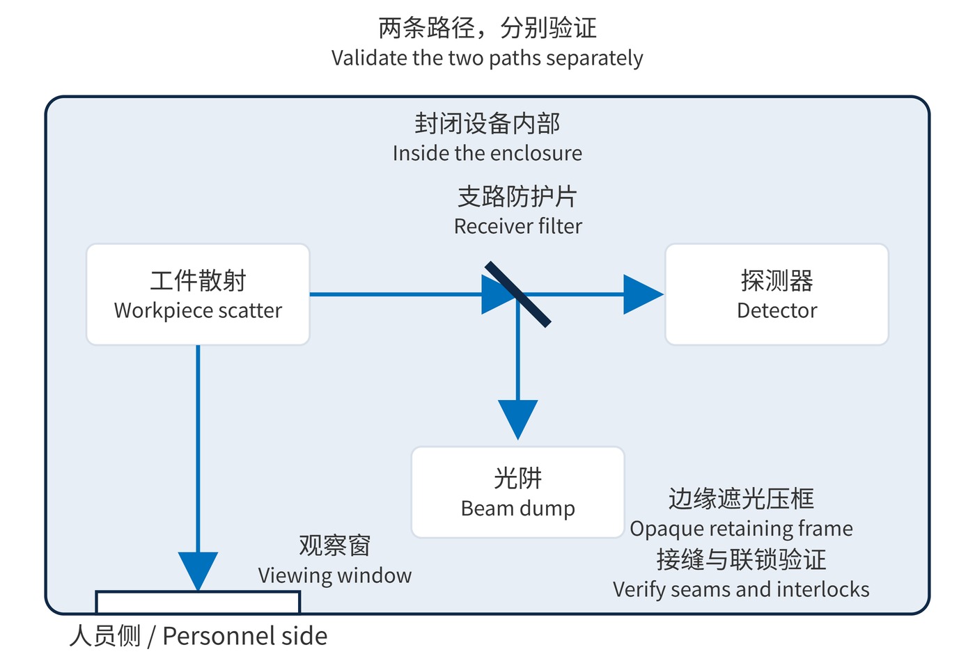
An observation window belongs on the enclosure’s protective boundary, away from foreseeable focused direct strikes. Opaque retaining frames must close edge paths. Assess seams, scattering and specular reflections together, and retain door interlocks.
As Fig. 2 shows, a receiver filter belongs upstream of the sensitive detector, in a section with a verified lower irradiance. Reflected energy terminates in a beam dump. A signal-path notch filter can reject the laser line, but a personnel-protection role requires corresponding safety validation of the assembly.
Visible light transmittance (VLT) describes photopically weighted brightness, not attenuation at the laser line. Blocking 532 nm can reduce brightness and color discrimination. Check illumination, alarm-light recognition and task visibility while preserving the required OD.
Acceptance requires evidence for spectral attenuation, irradiation endurance and accessible radiation from the assembled system, supported by operating conditions and test records.
 365nm Narrow Bandpass Filter | Ø50mm | T>90%
OT-HBP3659050
365nm Narrow Bandpass Filter; FWHM 10nm; transmission >90%; blocking OD5; size Ø50mm; AOI 0°.
 450nm Narrow Bandpass Filter | Ø50mm
OT-HBP4509050
450nm Narrow Bandpass Filter; FWHM 10nm; transmission >90%; blocking OD5; size Ø50mm; AOI 0°.
 525nm Narrow Bandpass Filter | Ø50mm
OT-HBP5259050
525nm Narrow Bandpass Filter; FWHM 10nm; transmission >90%; blocking OD5; size Ø50mm; AOI 0°.
Send us your drawing and spectral targets — an engineer replies with a feasibility check and quotation within one business day.