Original content by the OOTEE Optics editorial team, drawn from first-hand production line and inspection data. Please credit the source when republishing.
Given limits in expertise and test conditions, the theories, parameters and conclusions here carry no guarantee of absolute accuracy. For technical learning and exchange only - never the sole basis for design, acceptance or selection. Corrections welcome.
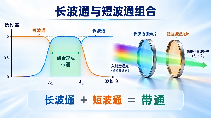
A longpass transmits above its lower spectral edge; a shortpass transmits below its upper edge. In series, they transmit their shared wavelength range. That creates a bandpass response, but a narrowband replacement must also meet throughput, bandwidth and blocking requirements.
Consider a design target of center wavelength (CWL) 780 nm, full width at half maximum (FWHM) 20 nm and out-of-band optical density (OD) 6. Buying a 770 nm longpass and a 790 nm shortpass does not establish compliance. All numerical specifications here are illustrative design targets, not product claims.
For a single pass, with inter-filter reflections and stray-light paths neglected, Ttotal(λ) = Tlong(λ) × Tshort(λ). Use fractional transmission: two filters transmitting 95% at the signal wavelength deliver 90.25% together. Fig. 1 shows how the two edges generate a bandpass.
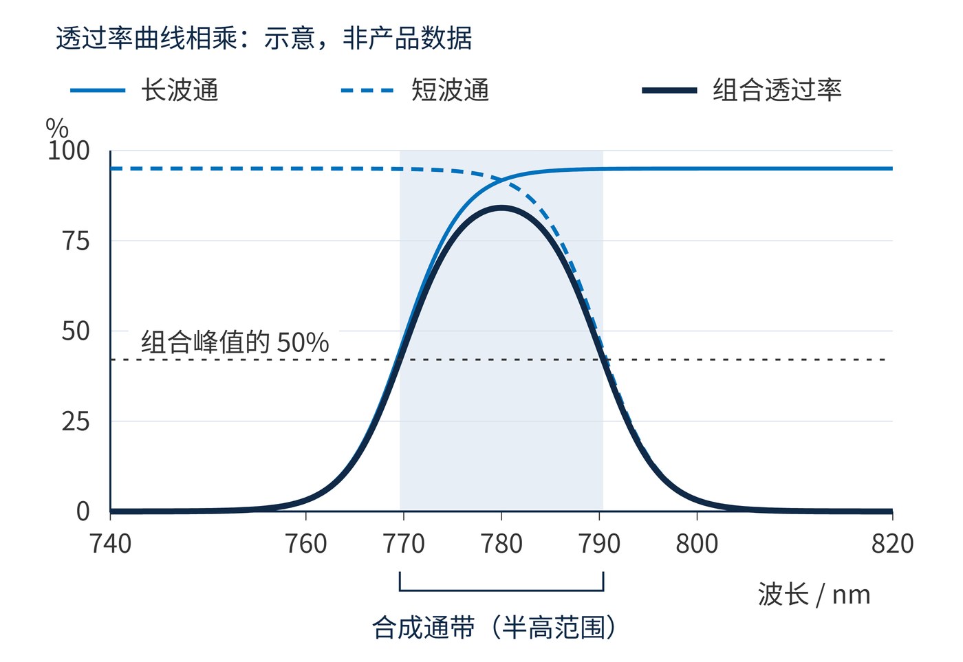
Finite edge slopes change the result. As the edges approach, their transition regions overlap, lowering the peak and potentially eliminating the flat top. In this schematic, each filter has a 95% plateau, yet neither reaches it at 780 nm. The combined peak is about 84%, rather than 90.25%.
Find FWHM from the two crossings at half the new combined peak. Separately find the interval meeting the absolute minimum transmission. A filter pair can have a plausible FWHM while failing the required throughput throughout that interval. Neither width is guaranteed by subtracting the nominal edge wavelengths; the drawing defines no production tolerances.
With OD = −log10(T), the single-pass model adds optical densities at each wavelength. It does not add headline ratings across different blocking regions. On the short-wavelength side, the longpass usually supplies most rejection; on the long-wavelength side, the shortpass does. OD3 followed by 95% transmission gives approximately OD3.02, not OD6.
Reflective filters mounted close and parallel can recycle rejected light between them, giving it further opportunities to escape through the pair. Measured rejection may then fall short of the product prediction. Scatter and light bypassing the mounts also raise the background. A blocking shortfall is therefore relative to a target or model; adding a filter does not inherently reduce single-pass OD.
OD6 means transmission no greater than 0.0001% at each specified wavelength. A result at one laser line does not qualify the full stopband. Inspect distant spectral regions where either filter may transmit again: a leakage window matters whenever the detector remains responsive there, even if it lies far from the desired band.
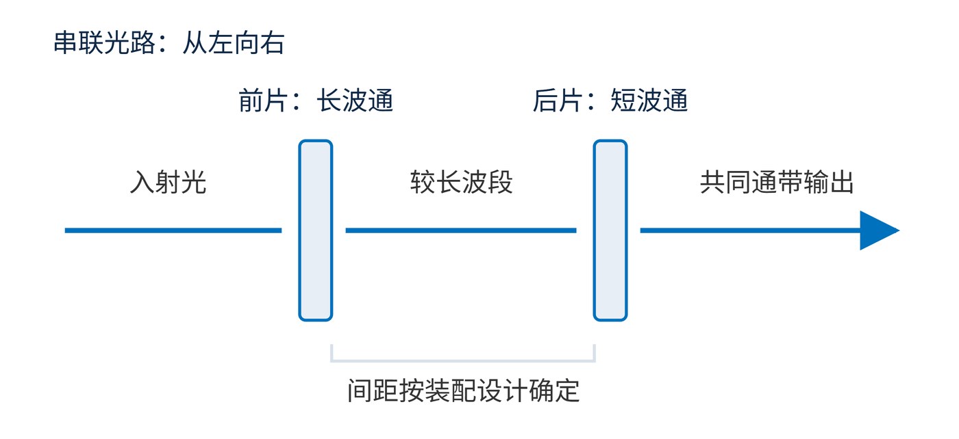
The drawing shows transmitted light only and does not prescribe contact mounting. Spacing, slight tilts and beam dumps may help remove returned light, but there is no universal tilt angle. Remeasure after any adjustment. Data at 0° cannot automatically qualify tilted filters or a converging beam.
Record beam cone angle, illuminated aperture and background subtraction with the assembly data. If a reading reaches the instrument floor, report only the OD lower bound supported by that measurement. Do not extrapolate a deeper value. An assembly with no continuous interval above the minimum transmission fails its throughput requirement even when its half-maximum width passes.
Broadband illumination shaping, machine-vision background reduction and exploratory wavelength selection benefit from independently adjustable edges. The pair is viable when the signal has spectral margin and the system can accommodate its throughput loss and physical thickness.
Weak fluorescence, rejection of a strong nearby laser line, or a stable 1–3 nm window warrants comparison with a dedicated narrowband design. Evaluate integrated signal, residual background and tolerance across builds. Component count and initial price do not determine equivalence.
For purchasing, make the assembled spectrum and mounting conditions part of acceptance. Agree when requalification is needed after replacing either element. Two individually acceptable filters are not necessarily interchangeable in every pair: accumulated edge errors can change the usable window across assemblies from the same batch.
For basic filter categories, see the cut-on and cut-off wavelengths explained. Qualify substitution through assembled transmission measurements and system background tests using the intended beam geometry.
 365nm Narrow Bandpass Filter | Ø50mm | T>90%
OT-HBP3659050
365nm Narrow Bandpass Filter; FWHM 10nm; transmission >90%; blocking OD5; size Ø50mm; AOI 0°.
 450nm Narrow Bandpass Filter | Ø50mm
OT-HBP4509050
450nm Narrow Bandpass Filter; FWHM 10nm; transmission >90%; blocking OD5; size Ø50mm; AOI 0°.
 525nm Narrow Bandpass Filter | Ø50mm
OT-HBP5259050
525nm Narrow Bandpass Filter; FWHM 10nm; transmission >90%; blocking OD5; size Ø50mm; AOI 0°.
Send us your drawing and spectral targets — an engineer replies with a feasibility check and quotation within one business day.



