Original content by the OOTEE Optics editorial team, drawn from first-hand production line and inspection data. Please credit the source when republishing.
Given limits in expertise and test conditions, the theories, parameters and conclusions here carry no guarantee of absolute accuracy. For technical learning and exchange only - never the sole basis for design, acceptance or selection. Corrections welcome.
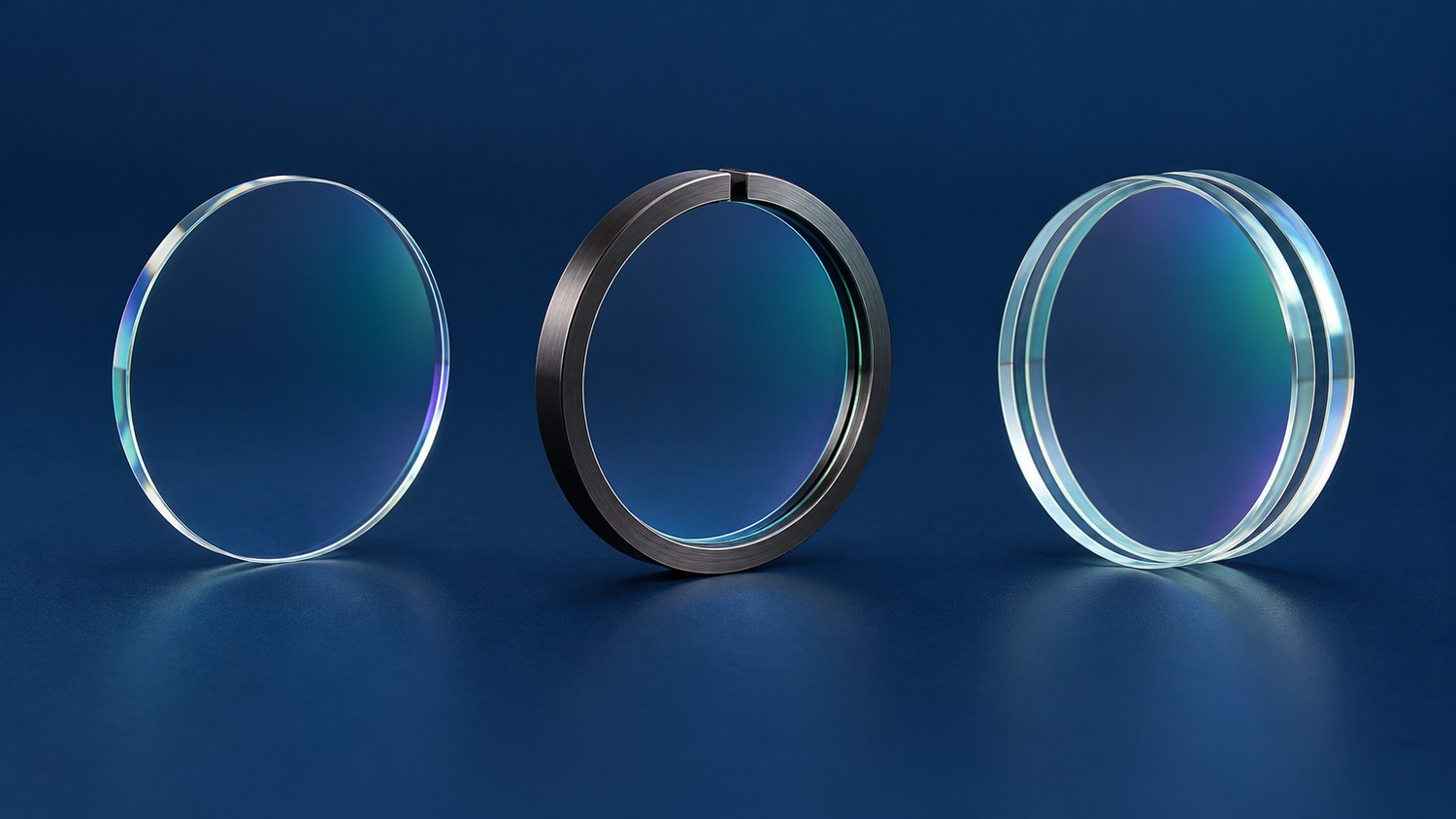
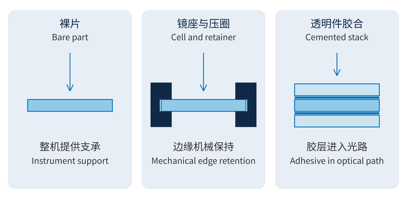
A bare part leaves positioning and retention to the instrument designer. A ring or cell supplies mechanical datums and holds the optic against a seat. A cemented assembly uses adhesive between optical elements or between an optic and its support. Packaging in this context includes the working support and environmental barrier, as well as protection during transport.
Figure 1 compares the interfaces rather than optical performance grades. Edge bonding normally keeps adhesive outside the beam; full-face cementing puts it in the optical path. Two transparent plates mechanically holding a filter with air gaps do not constitute a cemented assembly. An edge seal alone does not establish hermeticity.
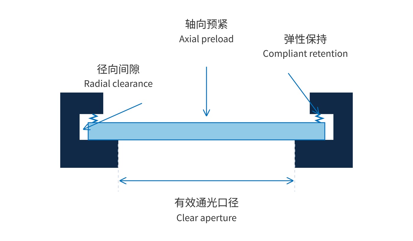
Outside diameter is not clear aperture. A 25 mm disc with 1.5 mm of radial overlap from its retainer has a nominal 22 mm opening before decenter and other allowances. For a collimated circular beam, a useful first check is:
$$D_{\mathrm{clear}} \geq \frac{D_{\mathrm{beam}}}{\cos\theta}+2e$$
Here $D_{\mathrm{beam}}$ is measured normal to propagation, $\theta$ is the angle of incidence (AOI), and $e$ is a lateral allowance on each side. An 18 mm beam at 30° with 0.5 mm per side needs about 21.8 mm. A 22 mm opening leaves little margin. Diverging beams require a separate ray analysis.
Differential expansion also changes the fit. For approximately equal glass and seat radii, the change in one-sided radial clearance is:
$$\Delta c \approx (\alpha_{\mathrm{mount}}-\alpha_{\mathrm{glass}})r\Delta T$$
With assumed expansion coefficients of 23 × 10⁻⁶/K and 7 × 10⁻⁶/K, a 12.5 mm radius and cooling by 60 °C reduce clearance by roughly 12 μm. This free-expansion estimate does not predict stress in an interference fit or bonded joint.
As Figure 2 shows, radial clearance accommodates movement while axial preload maintains seating. Excess preload can deform glass or damage edges; inadequate retention allows motion. Retainer torque must be established for the actual design using assembled optical results.
Specify mechanical interfaces alongside spectral requirements. An illustrative narrow bandpass filter might require a center wavelength (CWL) of 780 nm, full width at half maximum (FWHM) of 20 nm and blocking optical density (OD) of OD6. The blocking range, transmission and AOI must also be stated, together with whether acceptance applies to the bare or assembled optic.
| Option | Suitable starting point | Specify and verify |
|---|---|---|
| Bare part | Existing precision support and clean assembly process | Dimensions, support zones, orientation and handling edges |
| Ring or cell | Replaceability and repeatable mechanical datums | Clear aperture, axial datum, decenter, tilt and retention |
| Cemented assembly | Compact geometry with a qualified bonding process | Bond location, thickness, cure, void limits and repairability |
For full-face bonds, adhesive transmission, refractive index, fluorescence and aging belong in the optical specification. Edge bonds still require control of shrinkage and volatile contamination. Replacing air at a coated interface with adhesive can change its response, so the original air-tested spectrum cannot automatically qualify the bonded stack.
Compare spectra and the required wavefront or imaging metric before and after assembly, then repeat after the specified thermal and vibration exposure. Keep orientation and measurement position consistent to separate mounting effects from intrinsic factors such as coating stress.
Instruments with frequent wavelength changes benefit from removable cells, although tilt still needs checking after replacement. A compact machine vision filter can enter an existing barrel as a bare disc if the retainer clears the beam and edge scatter is controlled. Weak-signal fluorescence instruments should test adhesive background at the actual excitation wavelength.
Protected detector windows may combine a filter with transparent plates. Specify air gaps, edge bonds or full-face cementing explicitly. A clean shipping container protects the part; its cushioning material is not automatically qualified as a permanent support.
 365nm Narrow Bandpass Filter | Ø50mm | T>90%
OT-HBP3659050
365nm Narrow Bandpass Filter; FWHM 10nm; transmission >90%; blocking OD5; size Ø50mm; AOI 0°.
 450nm Narrow Bandpass Filter | Ø50mm
OT-HBP4509050
450nm Narrow Bandpass Filter; FWHM 10nm; transmission >90%; blocking OD5; size Ø50mm; AOI 0°.
 525nm Narrow Bandpass Filter | Ø50mm
OT-HBP5259050
525nm Narrow Bandpass Filter; FWHM 10nm; transmission >90%; blocking OD5; size Ø50mm; AOI 0°.
Send us your drawing and spectral targets — an engineer replies with a feasibility check and quotation within one business day.