Original content by the OOTEE Optics editorial team, drawn from first-hand production line and inspection data. Please credit the source when republishing.
Given limits in expertise and test conditions, the theories, parameters and conclusions here carry no guarantee of absolute accuracy. For technical learning and exchange only - never the sole basis for design, acceptance or selection. Corrections welcome.

Optical cold processing turns a blank into a part with controlled geometry and optical surfaces through cutting, grinding and polishing. “Cold” distinguishes this route from melting or hot forming. Friction still generates heat, so cooling and mounting stress remain process variables.
A filter manufacturing route continues through cleaning, coating and final inspection, although coating is a separate operation rather than cold processing. Fig. 1 shows the handoffs. Each stage must remove the previous stage’s defects while preserving enough stock for the next operation. The choice of substrate affects abrasive selection, handling and cleaning compatibility.
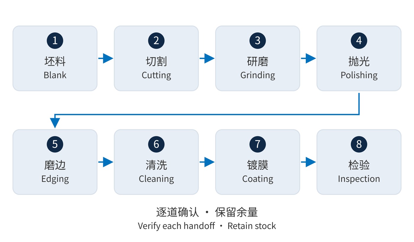
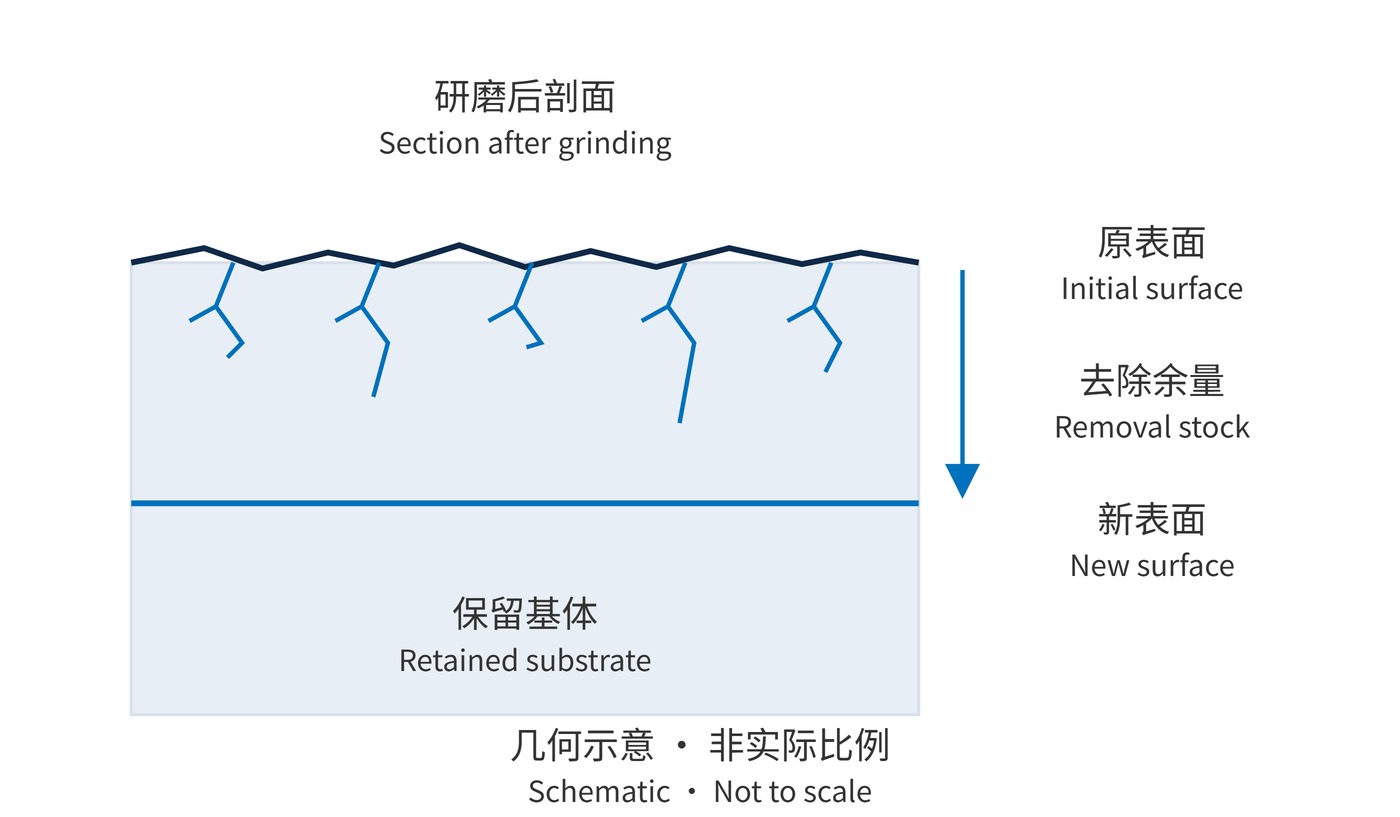
Incoming blanks are checked for material identity, inclusions, bubbles and stress. Cutting allowances account for kerf and later finishing. Coarse grinding establishes geometry; finer stages reduce pits and cracks left by earlier abrasives. Polishing improves texture and figure, but a glossy surface does not establish that subsurface damage (SSD) has disappeared. The same staged-removal practice appears in pre-polish grinding experiments published by the optical fabrication group at the University of Arizona: better to spend one more fine grinding step than push all removal into the last one.
For a two-sided flat, a useful stock budget is:
$$t_0=t_f+a_1+a_2$$
Here $t_0$ is the thickness entering the selected stage, $t_f$ the finished thickness, and $a_1$, $a_2$ the planned removals from each face. Saw kerf is outside this budget. Allowances must accommodate damage removal, figure correction and process variation.
The Preston relation approximates local removal in conventional polishing:
$$\frac{\mathrm{d}h}{\mathrm{d}t}=Kpv$$
Removal depth is $h$, contact pressure is $p$, and relative speed is $v$. The coefficient $K$ depends on the material, slurry and tool condition. This calibrated process model does not justify unlimited pressure or a universal polishing time.
As Fig. 2 illustrates, subsequent removal must extend beyond the damaged layer. Coarse-particle contamination can create fresh defects. Thickness, parallelism, figure, roughness and cosmetic defects therefore require separate acceptance checks.
A fabrication request needs a drawing revision, material, clear aperture and delivered condition. The example below is a requirements illustration, not a general capability claim. Figure tolerances need a test wavelength, aperture, support condition and stated metric.
| Handoff item | Example requirement | Conditions to agree |
|---|---|---|
| Size and thickness | Diameter 25.0 ±0.1 mm; thickness 2.0 ±0.05 mm | Before or after coating; measurement locations |
| Surface figure | Peak-to-valley ≤λ/4 at λ=632.8 nm | 22 mm clear aperture; low-stress support |
| Surface roughness | Root mean square ≤1 nm | Scan area, spatial bandwidth and instrument method |
| Edges and cleanliness | Bevel 0.2 mm ×45° | Chip limits, cleaning and packaging |
Edging establishes the final outline and removes sharp edges; it may occur earlier when the mounting route requires it. Thin parts need particular control of clamping and chipping. Cleaning must remove slurry and mounting residues without attacking the substrate. Inspect after rinsing and drying, then protect the part for coating or shipment. Ultrasonic treatment needs compatibility checks.
A finished narrow bandpass filter also needs independent spectral requirements: for example, center wavelength (CWL) 780 nm, full width at half maximum (FWHM) 20 nm, optical density (OD) 6 and angle of incidence (AOI) 0°. OD6 requires a defined blocking wavelength range. Substrate inspection alone cannot establish these coated-part results.
A machine vision window balances mounting fit, transmitted image quality and cleaning durability. A thin substrate can change shape after release from its fixture, making representative support conditions essential during measurement. Laser optics demand additional attention to contamination, residual damage and edge flaws; appearance inspection does not certify a laser damage threshold.
Weak-signal detection combines low substrate scatter with adequate spectral blocking. Final acceptance should join dimensional, surface and spectral records with any specified environmental tests. Material, fabrication and coating batch identifiers preserve traceability. Large thin parts also require recorded measurement locations to reveal spatial variation.
 365nm Narrow Bandpass Filter | Ø50mm | T>90%
OT-HBP3659050
365nm Narrow Bandpass Filter; FWHM 10nm; transmission >90%; blocking OD5; size Ø50mm; AOI 0°.
 450nm Narrow Bandpass Filter | Ø50mm
OT-HBP4509050
450nm Narrow Bandpass Filter; FWHM 10nm; transmission >90%; blocking OD5; size Ø50mm; AOI 0°.
 525nm Narrow Bandpass Filter | Ø50mm
OT-HBP5259050
525nm Narrow Bandpass Filter; FWHM 10nm; transmission >90%; blocking OD5; size Ø50mm; AOI 0°.
Send us your drawing and spectral targets — an engineer replies with a feasibility check and quotation within one business day.