Original content by the OOTEE Optics editorial team, drawn from first-hand production line and inspection data. Please credit the source when republishing.
Given limits in expertise and test conditions, the theories, parameters and conclusions here carry no guarantee of absolute accuracy. For technical learning and exchange only - never the sole basis for design, acceptance or selection. Corrections welcome.
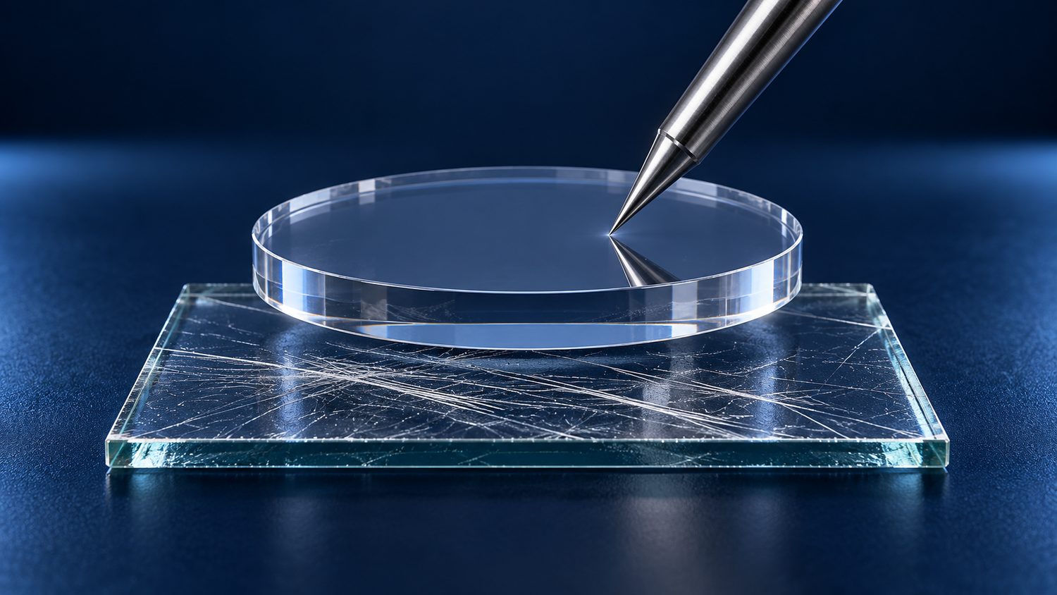
Optical sapphire is single-crystal aluminium oxide, usually colourless in high-purity grades. Its useful combination is a hard exposed surface and broad optical transmission. For equipment subject to dust, cleaning or particle-laden flow, maintaining that surface can matter more than achieving the highest transmission on a new window.
Sapphire has a Mohs hardness of 9; ordinary glass is typically around 5–6. These are scratch-resistance rankings, not a linear scale. They do not establish a tenfold hardness advantage. A stylus comparison illustrates behaviour under one set of contact conditions, rather than certifying abrasion resistance.
A hard crystal can still fracture. Edge defects, impact and concentrated mounting forces remain concerns. After coating, the exposed layer determines the first contact with cleaning tools and particles; the substrate hardness does not certify coating durability.
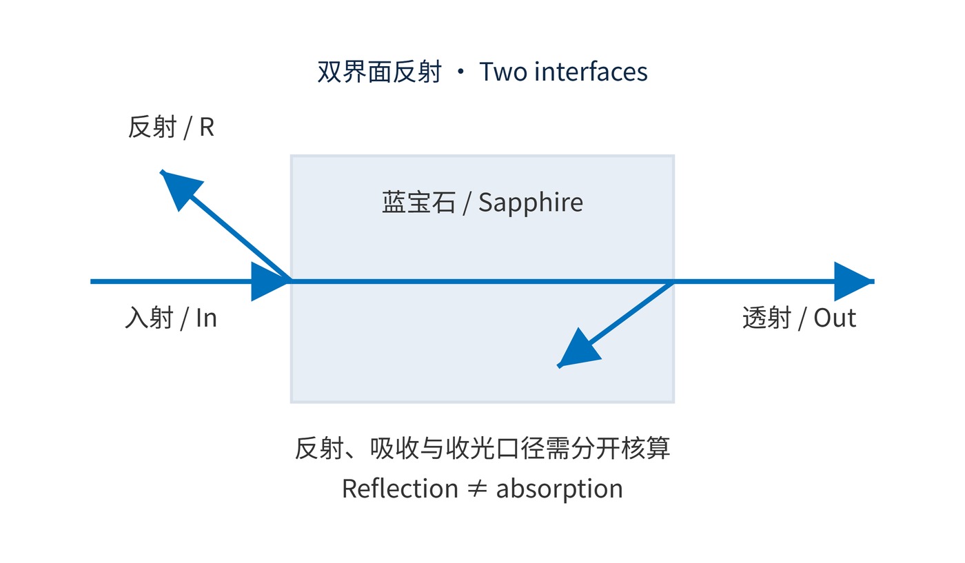
Fig. 1 separates interface reflection from light travelling through the crystal. For normal incidence from air, the power reflectance of one uncoated surface is:
$$R = \left(\frac{n-1}{n+1}\right)^2$$
Using a representative visible index of $n=1.76$ gives approximately 7.6% per surface. For a lossless parallel plate, summing incoherent multiple reflections collected in the forward direction gives:
$$T = \frac{(1-R)^2}{1-R^2}=\frac{1-R}{1+R}\approx 0.859$$
Thus, about 86% transmission need not imply 14% absorption. Restricted collection can lower the measured value, while coherent laser illumination may produce interference fringes. This calculation is an illustration, not a production acceptance limit.
Internal transmission follows $T_{\mathrm{int}}=\exp(-\alpha d)$ in a homogeneous absorbing medium. Both thickness $d$ and the wavelength-dependent absorption coefficient $\alpha$ matter. Sapphire generally transmits well through the visible and near infrared, but a nominal range near 200–5000 nm does not guarantee high transmission throughout. Check the actual grade and thickness near either absorption edge. Sapphire is unsuitable for an 8000–14000 nm thermal-imaging window.
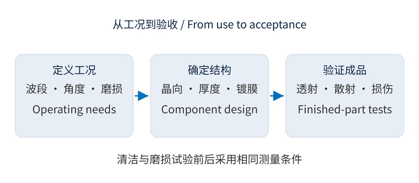
Start with wavelength, angle of incidence (AOI), polarisation, thickness and cleaning conditions. Fig. 2 shows the acceptance sequence: application conditions first, finished-part measurements last.
| Item | Example requirement | Conditions to record |
|---|---|---|
| Finished transmission | Minimum ≥95% over 800–900 nm | 1.0 mm thickness, AOI 0°, two-sided antireflection coating; target requiring verification |
| Crystal orientation | C-plane cut, optical axis near the surface normal | Orientation tolerance, beam cone and polarisation |
| Mechanical design | 25.0 mm diameter, 1.0 mm thickness | Tolerances, bevel, support aperture, pressure differential and cleaning test |
Sapphire is birefringent. Propagation along its optical axis reduces intrinsic birefringence effects, but oblique rays, converging beams and stress still require assessment. The example thickness is not a pressure-rating recommendation.
For a coated bandpass component, specify centre wavelength (CWL), full width at half maximum (FWHM) and optical density (OD) separately. CWL 850 nm, FWHM 20 nm and OD4 blocking over 400–750 nm would be coating targets, not properties supplied by the crystal.
Industrial imaging windows, frequently cleaned process ports and exposed optical probes can benefit from scratch resistance. Evaluate transmission, scatter and image contrast after representative wear, rather than comparing only pristine samples.
A separate sapphire cover can protect a near-infrared filter behind it and simplify replacement. Depositing the filter directly on sapphire reduces part count but makes coating durability central. Hot observation ports additionally need thermal-gradient, seal and mounting analysis.
Property data should come from the supplier data sheet for the specified orientation, grade and thickness, with test conditions stated.
A sound specification joins minimum optical throughput, acceptable surface damage and mechanical margin under the same operating conditions.
 365nm Narrow Bandpass Filter | Ø50mm | T>90%
OT-HBP3659050
365nm Narrow Bandpass Filter; FWHM 10nm; transmission >90%; blocking OD5; size Ø50mm; AOI 0°.
 450nm Narrow Bandpass Filter | Ø50mm
OT-HBP4509050
450nm Narrow Bandpass Filter; FWHM 10nm; transmission >90%; blocking OD5; size Ø50mm; AOI 0°.
 525nm Narrow Bandpass Filter | Ø50mm
OT-HBP5259050
525nm Narrow Bandpass Filter; FWHM 10nm; transmission >90%; blocking OD5; size Ø50mm; AOI 0°.
Send us your drawing and spectral targets — an engineer replies with a feasibility check and quotation within one business day.



