Original content by the OOTEE Optics editorial team, drawn from first-hand production line and inspection data. Please credit the source when republishing.
Given limits in expertise and test conditions, the theories, parameters and conclusions here carry no guarantee of absolute accuracy. For technical learning and exchange only - never the sole basis for design, acceptance or selection. Corrections welcome.
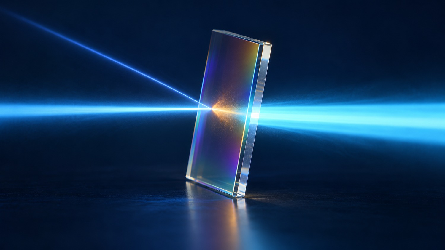
Transmission $T$, reflection $R$ and absorptance $A$ describe the fractions of incident optical power that pass through a filter, return to the incident side, or are absorbed within it. They share one energy budget at each wavelength. This discussion assumes a passive component without gain or appreciable fluorescence or wavelength conversion.
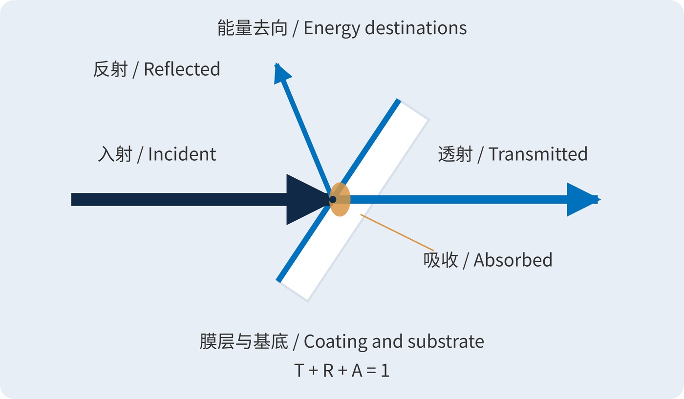
As Fig. 1 shows, rejecting light does not specify its destination. Absorption generally becomes heat; the warm glow is a visual convention, not a prediction of visible emission. A useful specification therefore addresses transmitted power, reflected power and deposited power together.
$$T(\lambda)+R(\lambda)+A(\lambda)=1$$
Here, $T$ and $R$ include all light leaving into their respective hemispheres. Measurements limited to the direct beam and specular reflection can miss scattered light and incorrectly count it as absorption.
Low-loss dielectric coatings mainly redistribute power through interference. Absorbing glass and lossy coatings can deposit a much larger fraction inside the component. Substrate losses, the rear surface and internal reflections all contribute, so acceptance data should describe the complete filter.
Optical density (OD) quantifies transmission attenuation using fractional, dimensionless transmittance:
$$\mathrm{OD}(\lambda)=-\log_{10}T(\lambda)$$
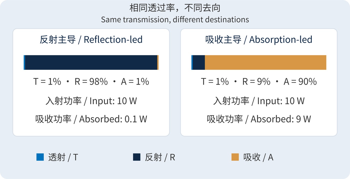
OD6 means $T=10^{-6}$, or 0.0001%. It says nothing about how the remainder divides between reflection and absorption. Fig. 2 compares two hypothetical budgets at the same wavelength and the same 1% transmission; these are illustrative values, not product data.
For a narrow-line continuous source, absorbed power is approximately:
$$P_{\mathrm{abs}}=A(\lambda_0)P_{\mathrm{in}}$$
At 10 W incident power, 1% absorption deposits 0.1 W, while 90% deposits 9 W. Broadband sources require integration over the incident power spectrum. Temperature rise also depends on spot size and thermal resistance. Short pulses require a separate assessment of fluence and damage mechanisms.
A center wavelength (CWL) of 780 nm, full width at half maximum (FWHM) of 20 nm, minimum passband transmission of 90% and OD6 blocking over 400–700 nm define useful spectral requirements. They do not specify where rejected energy goes.
Add the angle of incidence (AOI), for example 0°, polarization, angular distribution, illumination direction and temperature. Set reflection or absorption limits where the actual source is powerful. Tilting a filter can redirect return light, but changes its spectral and polarization response; verify it at the installed angle.
| System priority | Additional constraint | Acceptance focus |
|---|---|---|
| Limit filter heating | Maximum absorption in strong source bands | Deposited power, spot size and thermal path |
| Protect the source from feedback | Maximum power returning to the source | Reflection direction and collection geometry |
| Detect weak signals | Passband floor and stopband transmission ceiling | Instrument dynamic range and stray-light floor |
Reflective and absorptive neutral density filters with equal OD are therefore not automatically interchangeable. Request $T$ and $R$ under matching conditions, including collection geometry. When absorption is very small, measurement uncertainty can dominate the difference used to calculate it.
For procurement, distinguish a limit on total reflected power from a limit on power coupled back into the source. A high reflection coefficient can be acceptable when the beam is intercepted elsewhere. Conversely, even a modest reflection may be troublesome if the optical layout efficiently sends it back to a sensitive laser.
High-power illumination systems can reflect unwanted wavelengths toward a separate beam dump to reduce filter heating. The dump must still dissipate that power; a hot enclosure has not solved the thermal problem.
In fluorescence and multichannel instruments, a dichroic mirror uses reflection as a useful output port. Ghost paths and unwanted returns still need control. An absorptive attenuator may suit a compact module where return light is troublesome, provided its temperature, transmission stability and mounting stress remain acceptable.
Evaluate the filter with the source spectrum and mounting arrangement used in service. A transmission measurement made with a low-power probe establishes spectral throughput, but does not by itself demonstrate thermal performance under the operating beam. Record the illuminated area as well as the incident power when comparing candidate components.
Close the budget under one set of operating conditions: verify the spectrum, provide a controlled destination for reflected light, and confirm a thermal path for absorbed power. A transmission curve alone cannot establish all three.
 365nm Narrow Bandpass Filter | Ø50mm | T>90%
OT-HBP3659050
365nm Narrow Bandpass Filter; FWHM 10nm; transmission >90%; blocking OD5; size Ø50mm; AOI 0°.
 450nm Narrow Bandpass Filter | Ø50mm
OT-HBP4509050
450nm Narrow Bandpass Filter; FWHM 10nm; transmission >90%; blocking OD5; size Ø50mm; AOI 0°.
 525nm Narrow Bandpass Filter | Ø50mm
OT-HBP5259050
525nm Narrow Bandpass Filter; FWHM 10nm; transmission >90%; blocking OD5; size Ø50mm; AOI 0°.
Send us your drawing and spectral targets — an engineer replies with a feasibility check and quotation within one business day.



