Original content by the OOTEE Optics editorial team, drawn from first-hand production line and inspection data. Please credit the source when republishing.
Given limits in expertise and test conditions, the theories, parameters and conclusions here carry no guarantee of absolute accuracy. For technical learning and exchange only - never the sole basis for design, acceptance or selection. Corrections welcome.

A UV filter transmits a selected ultraviolet band while rejecting unwanted radiation. Deep ultraviolet (DUV) has no single boundary across all industries. Here the focus is approximately 200–300 nm, with discussion extending to 193 nm. DUV and UV-C are overlapping terms, rather than identical classifications.
Experience at 365 nm does not transfer directly to 248 nm, 266 nm or 193 nm. Absorption in substrates, coatings and surface residues can dominate the signal budget. Near and below 200 nm, oxygen along the beam path also deserves explicit attention. A filter that passes its component inspection may still deliver insufficient signal inside an instrument.
A clear substrate is only the first threshold: coating design, assembly cleanliness and the working environment decide the final result.
Photon energy rises as wavelength decreases. Photons at 248 nm and 193 nm carry approximately 5.00 eV and 6.42 eV, respectively. Defect generation and photochemical reactions may follow, although energy alone cannot predict service life.
$$E=\frac{hc}{\lambda}\approx\frac{1240\,\mathrm{eV\cdot nm}}{\lambda}$$
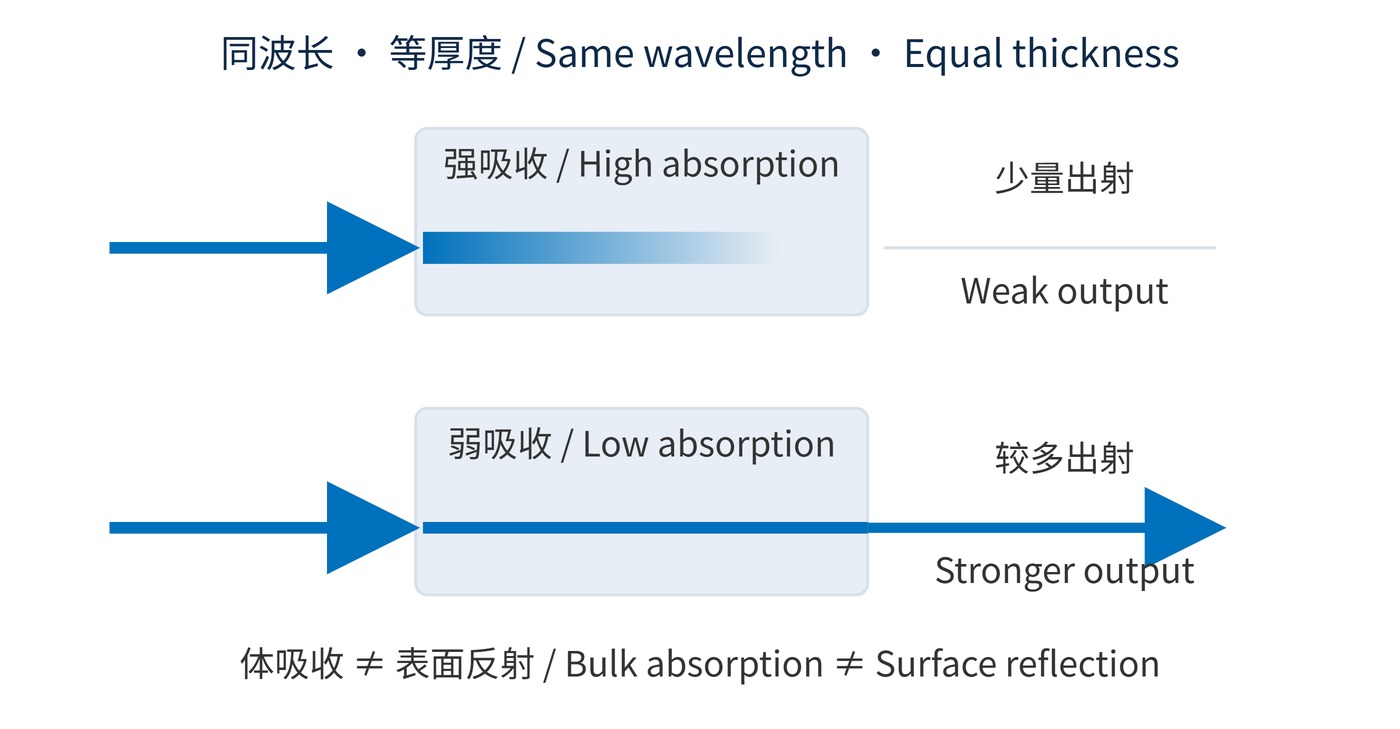
For a homogeneous substrate, internal single-pass transmission follows the absorption coefficient and thickness. It excludes interface reflection and therefore differs from finished-filter transmission.
$$T_{\mathrm{int}}(\lambda)=\exp[-\alpha(\lambda)d]$$
Use $\mathrm{cm^{-1}}$ for $\alpha$ and $\mathrm{cm}$ for $d$. Fig. 1 compares equal thicknesses: reducing bulk absorption can recover substantial light, but a thinner substrate cannot eliminate coating absorption or contamination.
Specify center wavelength (CWL), full width at half maximum (FWHM), optical density (OD), and angle of incidence (AOI). OD uses fractional transmission: OD4 means 0.01%, within a stated blocking interval.
$$\mathrm{OD}(\lambda)=-\log_{10}T(\lambda)$$
Coating materials need both useful index contrast and low extinction at the operating wavelength. An oxide with low visible absorption may be unsuitable at 193 nm. Changing the material pair also requires renewed checks of thickness, stress and environmental stability.
This makes transmission a shared budget rather than a substrate property. Light lost before the filter cannot be recovered by improving its peak transmission. Likewise, a clear substrate does not demonstrate that the deposited stack will remain low-loss at the same wavelength.
Start with the actual source wavelength and detector response. The following is an illustrative request for a 266 nm sensing channel, rather than a product specification or a guarantee for every DUV design.
| Item | Example requirement | Conditions to record |
|---|---|---|
| Passband | CWL 266 nm; FWHM 10 nm | AOI 0°; temperature 23 °C |
| Transmission | Minimum 40% over 264–268 nm | Finished-part measurement and uncertainty |
| Blocking | OD4 over 300–700 nm | Define additional blocking if detector response reaches 1100 nm |
| Lifetime | Agreed transmission-change limit after exposure | Wavelength, power density, duration and atmosphere |
“Silica” alone is an incomplete material specification. Request internal transmission at the intended thickness and wavelength, plus evidence of irradiation resistance. Check adhesives, enclosure windows and cleaning residues. Pulsed laser use additionally requires pulse duration, repetition rate, spot size and fluence.
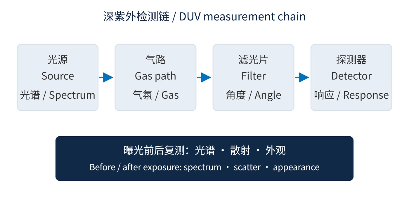
As Fig. 2 shows, acceptance extends through the detection chain. Verify source output, detector sensitivity and instrument stray light at the target wavelength. A signal below the measurement floor supports a bounded result, not an assertion of infinite OD.
Keep the sample and reference paths comparable. A different purge state or air-path length can be mistaken for a change in the component. For repeat measurements, preserve the illumination geometry and document any change to the detector or reference procedure.
Radiation monitoring at 254 nm or 265 nm needs rejection of longer-wavelength source emissions, weighted by detector response. Absorption spectroscopy also needs stable baselines and matching gas conditions for sample and reference measurements.
At 193 nm, assess purging or vacuum explicitly; the same requirement does not automatically apply at 254 nm. An experimental study published in Applied Optics documents oxygen absorption at 180–200 nm and the effect of purging. Record path length, gas purity and sealing alongside transmission data.
Laser systems need representative accumulated exposure tests. Compare spectra, scatter and appearance before and after irradiation to distinguish contamination, induced defects and immediate damage. An initial low-power scan cannot establish lifetime.
The exposure record should identify the conditions under which the result remains applicable. A stability claim without wavelength, dose and atmosphere gives little guidance for transferring the filter into another instrument.
A useful acceptance record ties spectral results to angle, atmosphere, measurement capability and exposure history so that system performance can be reproduced.
 365nm Narrow Bandpass Filter | Ø50mm | T>90%
OT-HBP3659050
365nm Narrow Bandpass Filter; FWHM 10nm; transmission >90%; blocking OD5; size Ø50mm; AOI 0°.
 450nm Narrow Bandpass Filter | Ø50mm
OT-HBP4509050
450nm Narrow Bandpass Filter; FWHM 10nm; transmission >90%; blocking OD5; size Ø50mm; AOI 0°.
 525nm Narrow Bandpass Filter | Ø50mm
OT-HBP5259050
525nm Narrow Bandpass Filter; FWHM 10nm; transmission >90%; blocking OD5; size Ø50mm; AOI 0°.
Send us your drawing and spectral targets — an engineer replies with a feasibility check and quotation within one business day.