Original content by the OOTEE Optics editorial team, drawn from first-hand production line and inspection data. Please credit the source when republishing.
Given limits in expertise and test conditions, the theories, parameters and conclusions here carry no guarantee of absolute accuracy. For technical learning and exchange only - never the sole basis for design, acceptance or selection. Corrections welcome.
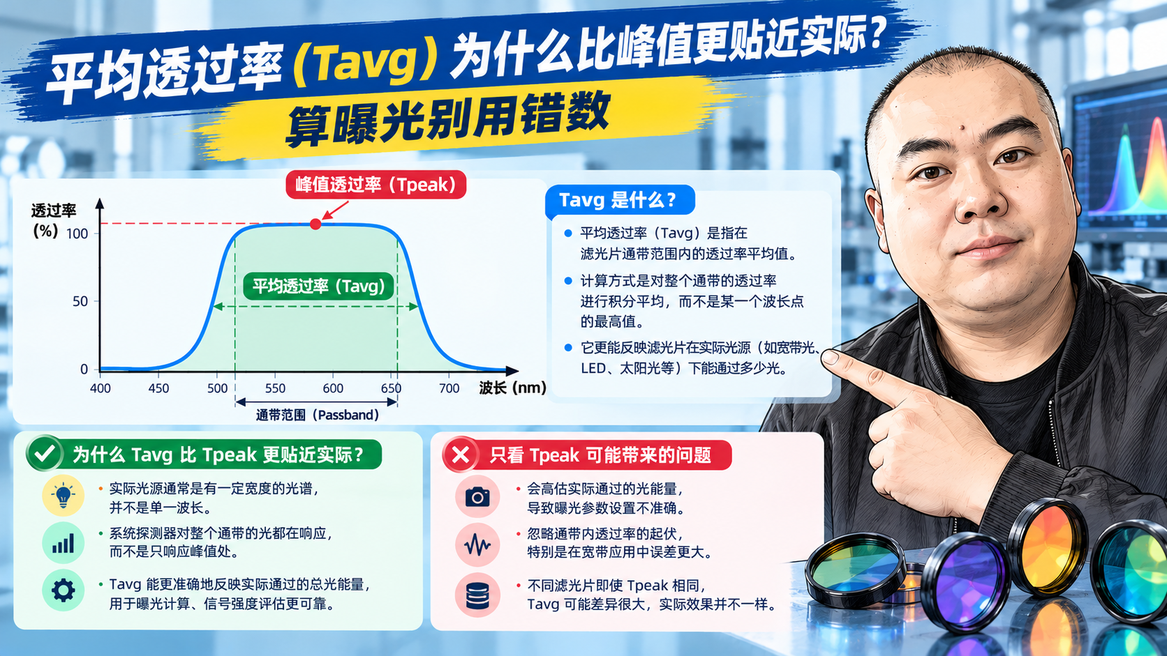
Average transmission (Tavg) is the mean transmission of a filter across a defined passband. If peak transmission is the best score, Tavg is the class average - and your system experiences the average, not the best.
Take a narrowband filter at CWL 532 nm with 10 nm FWHM and 92% peak. Because the curve is a smooth hump, its shoulders sit near half height and the average across the band is roughly 85%. Design your camera exposure around 92% and every frame comes out dark.
There is more: the source has finite spectral width and the detector response is not flat. Real flux is the integral of source spectrum x filter curve x detector response - and for that, Tavg is far closer than Tpeak.
The trouble is that "average" is not standardized. Three conventions are common:
| Convention | Method | Tendency |
|---|---|---|
| Average over the FWHM interval | Integrate only above the half-maximum points | Optimistic - excludes the weak shoulders |
| Average over the nominal passband | Integrate across e.g. 520-545 nm as stated | Middle ground, most common |
| Point-by-point average | Arithmetic mean sampled every 1 nm | Sensitive to sampling; lower for wide intervals |
A filter with soft shoulders may read Tavg 88% under the first convention and 82% under the third. The difference is in the math, not the glass. Before comparing two quotations, confirm how each vendor defines Tavg.
The gaps between them reveal the shape of the curve:
The surest way to judge flatness is to request the full spectral data file (CSV or Excel) and look at the passband yourself, rather than trusting three numbers.
Conversely, if the signal is plentiful and software normalizes the output, priority can shift to blocking depth and bandwidth instead.
Recommended form: "Tavg at least 85% from 520 to 545 nm, arithmetic mean at 1 nm steps". One sentence fixes the interval, the value and the method, leaving nothing to argue about later.
Need measured curves for comparison? Send your target parameters to sales@ootee.cn and we will supply full spectral data from the same batch, ready to import into your simulation.
 365nm Narrow Bandpass Filter | Ø50mm | T>90%
OT-HBP3659050
365nm Narrow Bandpass Filter; FWHM 10nm; transmission >90%; blocking OD5; size Ø50mm; AOI 0°.
 450nm Narrow Bandpass Filter | Ø50mm
OT-HBP4509050
450nm Narrow Bandpass Filter; FWHM 10nm; transmission >90%; blocking OD5; size Ø50mm; AOI 0°.
 525nm Narrow Bandpass Filter | Ø50mm
OT-HBP5259050
525nm Narrow Bandpass Filter; FWHM 10nm; transmission >90%; blocking OD5; size Ø50mm; AOI 0°.
Send us your drawing and spectral targets — an engineer replies with a feasibility check and quotation within one business day.



